Arduino-Controlled 28BYJ-48 Stepper Motor with ULN2003 Driver
Circuit Documentation
Summary
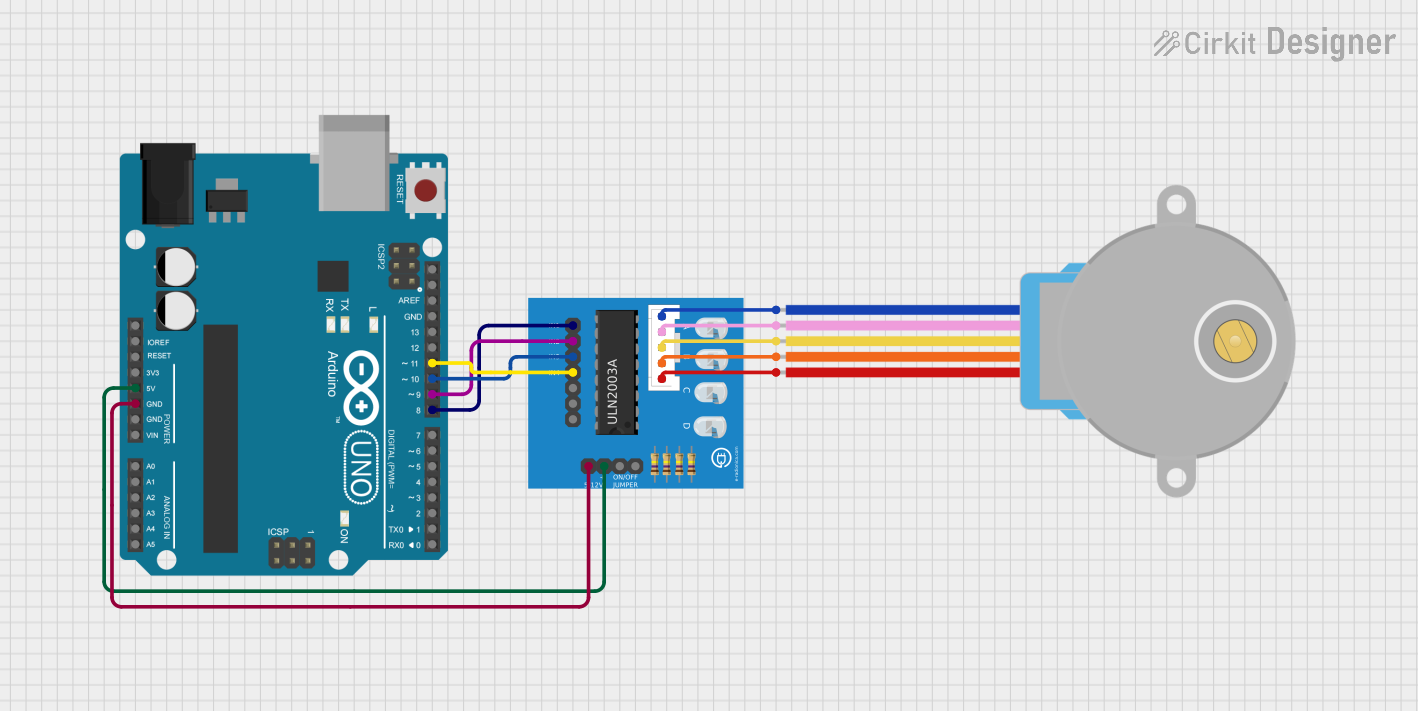
This circuit is designed to control a 28BYJ-48 Stepper Motor using an Arduino UNO microcontroller and a ULN2003A breakout board. The Arduino UNO provides the control signals to the stepper motor through the ULN2003A driver, which amplifies the signals to drive the motor coils. The circuit is powered by the Arduino's 5V output, which also powers the ULN2003A breakout board.
Component List
Arduino UNO
- Description: A microcontroller board based on the ATmega328P.
- Pins: UNUSED, IOREF, Reset, 3.3V, 5V, GND, Vin, A0-A5, SCL, SDA, AREF, D0-D13.
- Purpose: Acts as the main controller for the stepper motor, sending step commands and controlling the speed of the motor.
28BYJ-48 Stepper Motor
- Description: A small, 5-wire, unipolar stepper motor.
- Pins: BLUE, PINK, YELLOW, ORANGE, RED.
- Purpose: The actuator of the system, it converts electrical pulses into mechanical movement.
ULN2003A Breakout Board
- Description: A breakout board for the ULN2003A Darlington transistor array.
- Pins: In 1-4, In 5-7 (unused), 0V, +5V, ON/OFF jumper switch, BLUE wire, PINK wire, YELLOW wire, ORANGE wire, RED wire.
- Purpose: Interfaces between the Arduino UNO and the stepper motor, providing the necessary current to drive the motor coils.
Wiring Details
Arduino UNO
- 5V to ULN2003A breakout board +5V
- GND to ULN2003A breakout board 0V
- D11 to ULN2003A breakout board In 4
- D10 to ULN2003A breakout board In 3
- D9 to ULN2003A breakout board In 2
- D8 to ULN2003A breakout board In 1
28BYJ-48 Stepper Motor
- BLUE to ULN2003A breakout board BLUE wire
- PINK to ULN2003A breakout board PINK wire
- YELLOW to ULN2003A breakout board YELLOW wire
- ORANGE to ULN2003A breakout board ORANGE wire
- RED to ULN2003A breakout board RED wire
ULN2003A Breakout Board
- In 1-4 connected to Arduino UNO D8-D11
- +5V connected to Arduino UNO 5V
- 0V connected to Arduino UNO GND
- BLUE wire to Stepper Motor BLUE
- PINK wire to Stepper Motor PINK
- YELLOW wire to Stepper Motor YELLOW
- ORANGE wire to Stepper Motor ORANGE
- RED wire to Stepper Motor RED
Documented Code
Arduino UNO Code
// Arduino stepper motor control code
#include <Stepper.h> // Include the header file
// change this to the number of steps on your motor
#define STEPS 32
// create an instance of the stepper class using the steps and pins
Stepper stepper(STEPS, 8, 9, 10, 11);
int val = 0;

void setup() {
    Serial.begin(9600);
    stepper.setSpeed(200);
}

void loop() {
    if (Serial.available()>0)
{
     val = Serial.parseInt();
     stepper.step(val);
     Serial.println(val); //for debugging
}
}
Filename: sketch.ino
Description: This code snippet is responsible for controlling the stepper motor via the Arduino UNO. It initializes the stepper motor with the specified number of steps and sets up the pins connected to the ULN2003A breakout board. The loop function listens for serial input to determine the number of steps the motor should move.
Stepper Motor Code
The stepper motor itself does not have embedded code as it is directly controlled by the Arduino UNO through the ULN2003A breakout board.
ULN2003A Breakout Board Code
The ULN2003A breakout board does not require separate code as it is a hardware interface that operates based on the input signals from the Arduino UNO.