
Arduino MKR WiFi 1010 Basic Power Supply with Voltage Divider
View and Edit Project In Cirkit Designer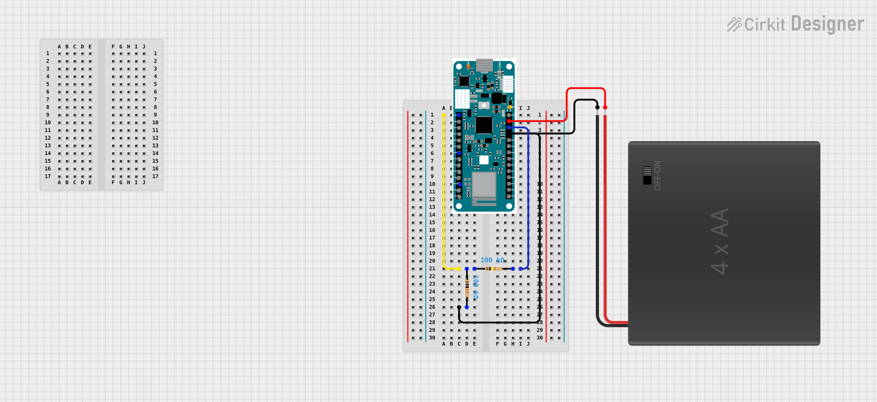
Circuit Documentation
Summary of the Circuit
This circuit consists of an Arduino MKR WiFi 1010 microcontroller, two resistors, and a 4xAA battery holder. The Arduino MKR WiFi 1010 is the central processing unit of the circuit, capable of executing embedded code and interfacing with various peripherals. The resistors are used to form a voltage divider or to limit current, depending on their placement in the circuit. The 4xAA battery holder provides the power source for the circuit.
Component List
Arduino MKR WiFi 1010
- Description: A microcontroller board based on the Atmel SAMD21 and a U-Blox ESP32 module for Wi-Fi connectivity.
- Pins: A0-A6, D0-D7, MOSI, SCK, MISO, SDA, SCL, RX, TX, RESET, GND, VCC, VIN, 5V.
4xAA Battery Holder
- Description: A battery holder for four AA batteries, providing a power source for the circuit.
- Pins: POS (positive terminal), NEG (negative terminal).
Resistor (100k Ohms)
- Description: A passive two-terminal electrical component that implements electrical resistance as a circuit element.
- Resistance: 100,000 Ohms.
Wiring Details
Arduino MKR WiFi 1010
- GND: Connected to the negative terminal (NEG) of the 4xAA battery holder and pin 2 of a 100k Ohm resistor.
- VCC: Connected to pin 2 of a different 100k Ohm resistor.
- VIN: Connected to the positive terminal (POS) of the 4xAA battery holder.
- A0: Connected to pin 1 of both 100k Ohm resistors.
4xAA Battery Holder
- POS: Connected to VIN on the Arduino MKR WiFi 1010.
- NEG: Connected to GND on the Arduino MKR WiFi 1010.
Resistor (100k Ohms)
- pin1: Connected to A0 on the Arduino MKR WiFi 1010.
- pin2: One resistor is connected to GND on the Arduino MKR WiFi 1010 and NEG on the 4xAA battery holder. The other resistor is connected to VCC on the Arduino MKR WiFi 1010.
Documented Code
No code has been provided for the microcontroller. When code is available, it should be documented here with explanations for each function and routine, including setup and loop functions, interrupt service routines, and any custom functions used to control peripherals or implement the circuit's functionality.
This documentation provides an overview of the circuit's components, their connections, and the intended functionality. Further details, such as the specific purpose of each resistor and the intended behavior of the microcontroller, would be necessary to fully understand the circuit's operation.