
ESP32-Based Smart Garden System with Wi-Fi Control and Sensor Integration
View and Edit Project In Cirkit Designer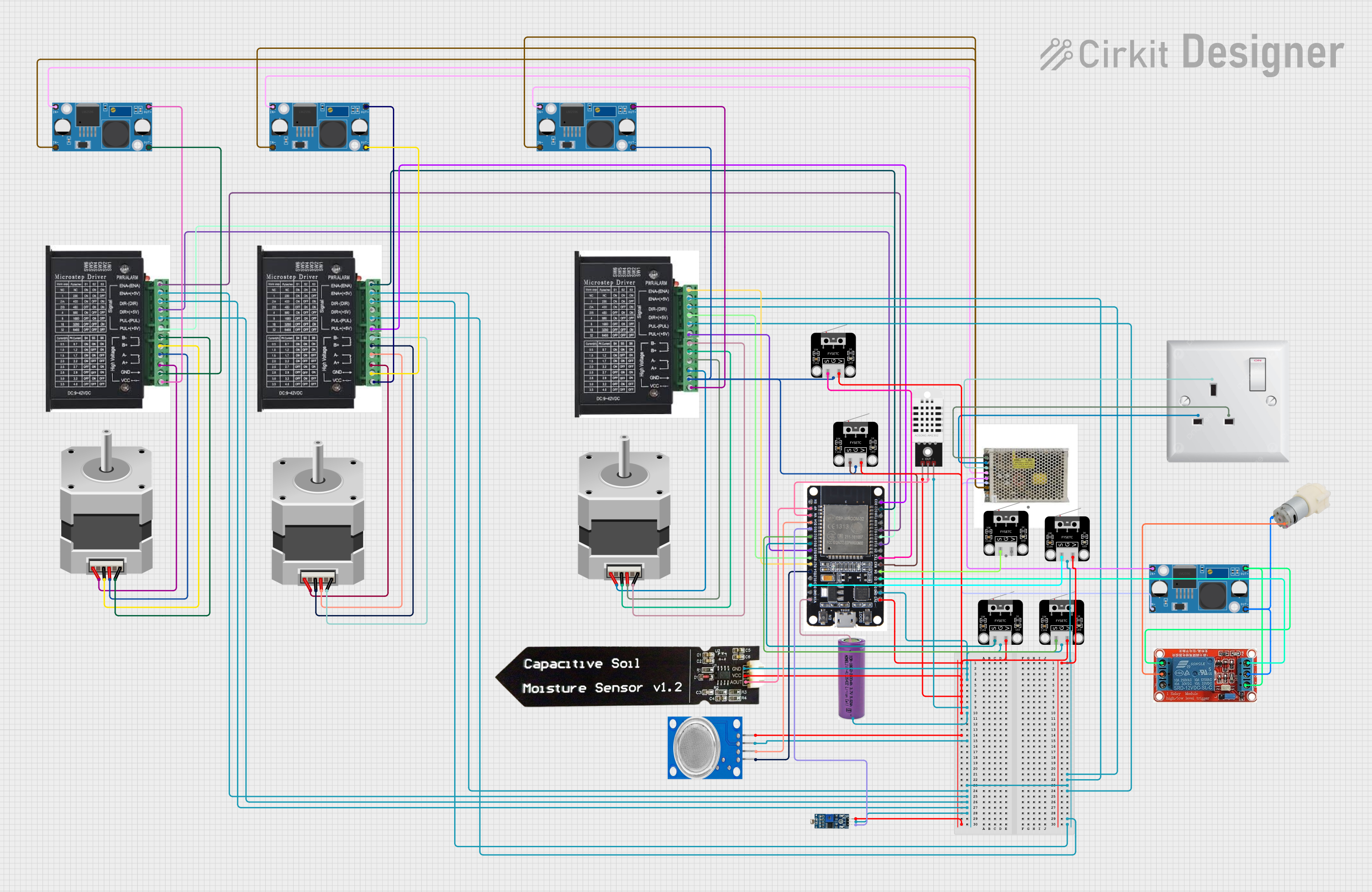
Circuit Documentation
Summary
This document provides a detailed overview of a circuit design that includes an ESP32 microcontroller, various sensors, stepper motors, stepper drivers, a relay, a water pump, and power supplies. The circuit is designed to interface with multiple sensors and actuators, providing a comprehensive control system.
Component List
ESP32
- Description: A powerful microcontroller with Wi-Fi and Bluetooth capabilities.
- Pins: EN, VP, VN, D34, D35, D32, D33, D25, D26, D27, D14, D12, D13, GND, VIN, 3V3, D15, D2, D4, RX2, TX2, D5, D18, D19, D21, RX0, TX0, D22, D23, BOOT
DHT22
- Description: A digital temperature and humidity sensor.
- Pins: +, Out, -
Stepper Motor (Bipolar)
- Description: A bipolar stepper motor used for precise control of rotational position.
- Pins: D, B, C, A
Stepper Driver
- Description: A driver module for controlling stepper motors.
- Pins: ENA, ENA -, DIR-, DIR+, PUL-, PUL +, B-, B+, A-, A+, GND, VCC
Capacitive Soil Moisture Sensor V1.2
- Description: A sensor for measuring soil moisture levels.
- Pins: GND, VCC, AOUT
Water Pump 12V
- Description: A 12V water pump for fluid transfer.
- Pins: +, -
LDR Module 3 Pin
- Description: A light-dependent resistor module for detecting light levels.
- Pins: VCC, GND, DO
Power Supply 24VDC
- Description: A power supply providing 24V DC output.
- Pins: L, N, E, V+, V-
12V Relay
- Description: A relay module for switching high-power devices.
- Pins: NO, COM, NC, IN, DC-, DC+
LM2956 Buck Converter DC-DC
- Description: A buck converter for stepping down voltage.
- Pins: OUT+, OUT-, IN+, IN-
MQ135
- Description: A gas sensor for detecting air quality.
- Pins: VCC, GND, A0, D0
AC Wall Plug Point
- Description: A standard AC wall plug point.
- Pins: E, N, L
3.3V Battery
- Description: A battery providing 3.3V output.
- Pins: +, -
Limit Switch
- Description: A switch for detecting physical limits or positions.
- Pins: S, G, V
Wiring Details
ESP32
- 3V3: Connected to VCC of Capacitive Soil Moisture Sensor V1.2, V of Limit Switches, + of DHT22, VCC of MQ135, and VCC of LDR Module 3 Pin.
- GND: Connected to GND of Capacitive Soil Moisture Sensor V1.2, G of Limit Switches, - of DHT22, - of 3.3V Battery, GND of MQ135, ENA -, PUL-, DIR- of Stepper Drivers, and GND of LDR Module 3 Pin.
- VP: Connected to AOUT of Capacitive Soil Moisture Sensor V1.2.
- VN: Connected to Out of DHT22.
- D34: Connected to A0 of MQ135.
- D35: Connected to DO of LDR Module 3 Pin.
- D32: Connected to S of Limit Switch.
- D33: Connected to S of Limit Switch.
- D25: Connected to PUL + of Stepper Driver.
- D26: Connected to DIR+ of Stepper Driver.
- D27: Connected to ENA of Stepper Driver.
- D14: Connected to D0 of MQ135.
- D13: Connected to S of Limit Switch.
- VIN: Connected to + of 3.3V Battery.
- D2: Connected to IN of 12V Relay.
- D4: Connected to S of Limit Switch.
- RX2: Connected to S of Limit Switch.
- TX2: Connected to S of Limit Switch.
- D18: Connected to DIR+ of Stepper Driver.
- D19: Connected to PUL + of Stepper Driver.
- D21: Connected to ENA of Stepper Driver.
- D22: Connected to ENA of Stepper Driver.
- D23: Connected to PUL + of Stepper Driver.
DHT22
- +: Connected to 3V3 of ESP32.
- Out: Connected to VN of ESP32.
- -: Connected to GND of ESP32.
Stepper Motor (Bipolar)
- D: Connected to B- of Stepper Driver.
- B: Connected to A- of Stepper Driver.
- C: Connected to B+ of Stepper Driver.
- A: Connected to A+ of Stepper Driver.
Stepper Driver
- ENA: Connected to D27 of ESP32.
- ENA -: Connected to GND of ESP32.
- DIR-: Connected to GND of ESP32.
- DIR+: Connected to D26 of ESP32.
- PUL-: Connected to GND of ESP32.
- PUL +: Connected to D25 of ESP32.
- B-: Connected to D of Stepper Motor.
- B+: Connected to C of Stepper Motor.
- A-: Connected to B of Stepper Motor.
- A+: Connected to A of Stepper Motor.
- GND: Connected to OUT- of LM2956 Buck Converter DC-DC.
- VCC: Connected to OUT+ of LM2956 Buck Converter DC-DC.
Capacitive Soil Moisture Sensor V1.2
- GND: Connected to GND of ESP32.
- VCC: Connected to 3V3 of ESP32.
- AOUT: Connected to VP of ESP32.
Water Pump 12V
- +: Connected to COM of 12V Relay.
- -: Connected to OUT- of LM2956 Buck Converter DC-DC.
LDR Module 3 Pin
- VCC: Connected to 3V3 of ESP32.
- GND: Connected to GND of ESP32.
- DO: Connected to D35 of ESP32.
Power Supply 24VDC
- L: Connected to L of AC Wall Plug Point.
- N: Connected to N of AC Wall Plug Point.
- E: Connected to E of AC Wall Plug Point.
- V+: Connected to IN+ of LM2956 Buck Converter DC-DC.
- V-: Connected to IN- of LM2956 Buck Converter DC-DC.
12V Relay
- NO: Connected to OUT+ of LM2956 Buck Converter DC-DC.
- COM: Connected to + of Water Pump 12V.
- NC: Not connected.
- IN: Connected to D2 of ESP32.
- DC-: Connected to OUT- of LM2956 Buck Converter DC-DC.
- DC+: Connected to OUT+ of LM2956 Buck Converter DC-DC.
LM2956 Buck Converter DC-DC
- OUT+: Connected to VCC of Stepper Driver, NO and DC+ of 12V Relay.
- OUT-: Connected to GND of Stepper Driver, - of Water Pump 12V, and DC- of 12V Relay.
- IN+: Connected to V+ of Power Supply 24VDC.
- IN-: Connected to V- of Power Supply 24VDC.
MQ135
- VCC: Connected to 3V3 of ESP32.
- GND: Connected to GND of ESP32.
- A0: Connected to D34 of ESP32.
- D0: Connected to D14 of ESP32.
AC Wall Plug Point
- E: Connected to E of Power Supply 24VDC.
- N: Connected to N of Power Supply 24VDC.
- L: Connected to L of Power Supply 24VDC.
3.3V Battery
- +: Connected to VIN of ESP32.
- -: Connected to GND of ESP32.
Limit Switch
- S: Connected to D32, D33, D13, D4, RX2, TX2 of