Cirkit Designer
Your all-in-one circuit design IDE
Home /
Project Documentation
Arduino-Controlled WS2812 RGB LED Matrix Display with Bit-Banged SPI
Circuit Documentation
Summary
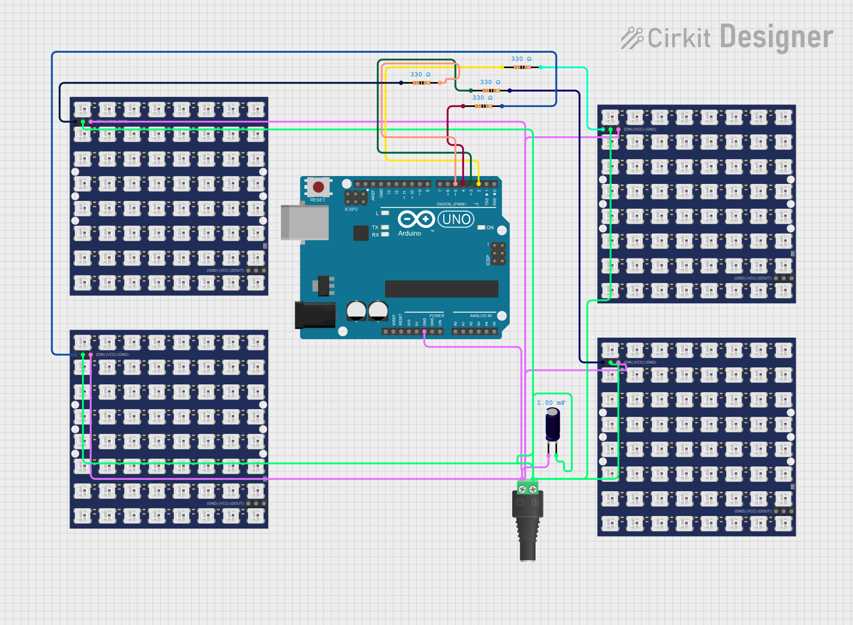
This circuit is designed to control a series of WS2812 RGB LED matrices using an Arduino UNO. The circuit includes power regulation, signal conditioning, and control logic to drive the LED matrices. The Arduino UNO is programmed to generate patterns on the LED matrices.
Component List
2.1mm Barrel Jack with Terminal Block
- Pins: POS, NEG
- Description: Power input connector
- Purpose: Provides power to the circuit
Electrolytic Capacitor
- Pins: +, -
- Description: 0.001 Farads
- Purpose: Stabilizes the power supply
WS2812 RGB LED matrix 8x8
- Pins: DIN, VCC, GND, DOUT
- Description: RGB LED matrix
- Purpose: Displays patterns controlled by the Arduino
Resistor (330 Ohms)
- Pins: pin1, pin2
- Description: 330 Ohms
- Purpose: Current limiting for data lines
Arduino UNO
- Pins: UNUSED, IOREF, Reset, 3.3V, 5V, GND, Vin, A0, A1, A2, A3, A4, A5, SCL, SDA, AREF, D13, D12, D11, D10, D9, D8, D7, D6, D5, D4, D3, D2, D1, D0
- Description: Microcontroller board
- Purpose: Controls the LED matrices
Wiring Details
2.1mm Barrel Jack with Terminal Block
POS connected to:
- VCC of all WS2812 RGB LED matrices
- of Electrolytic Capacitor
NEG connected to:
- GND of all WS2812 RGB LED matrices
- GND of Arduino UNO
- of Electrolytic Capacitor
Electrolytic Capacitor
+ connected to:
- POS of 2.1mm Barrel Jack with Terminal Block
- connected to:
- NEG of 2.1mm Barrel Jack with Terminal Block
WS2812 RGB LED matrix 8x8
DIN connected to:
- pin2 of Resistor (330 Ohms) for each matrix
VCC connected to:
- POS of 2.1mm Barrel Jack with Terminal Block
GND connected to:
- NEG of 2.1mm Barrel Jack with Terminal Block
DOUT not connected in this configuration
Resistor (330 Ohms)
pin1 connected to:
- D2 of Arduino UNO (for one resistor)
- D3 of Arduino UNO (for one resistor)
- D4 of Arduino UNO (for one resistor)
- D5 of Arduino UNO (for one resistor)
pin2 connected to:
- DIN of WS2812 RGB LED matrix 8x8 (one resistor per matrix)
Arduino UNO
D2 connected to:
- pin1 of one Resistor (330 Ohms)
D3 connected to:
- pin1 of one Resistor (330 Ohms)
D4 connected to:
- pin1 of one Resistor (330 Ohms)
D5 connected to:
- pin1 of one Resistor (330 Ohms)
GND connected to:
- NEG of 2.1mm Barrel Jack with Terminal Block
Code Documentation
sketch.ino
// This version uses bit-banged SPI.
// If you see tearing (jagged edges on the circles) try the version
// which uses AVR's hardware SPI peripheral:
// https://wokwi.com/arduino/projects/318868939929027156

#define CLK 12
#define DIN 11
#define CS  10
#define X_SEGMENTS   4
#define Y_SEGMENTS   4
#define NUM_SEGMENTS (X_SEGMENTS * Y_SEGMENTS)

// a framebuffer to hold the state of the entire matrix of LEDs
// laid out in raster order, with (0, 0) at the top-left
byte fb[8 * NUM_SEGMENTS];

void shiftAll(byte send_to_address, byte send_this_data)
{
  digitalWrite(CS, LOW);
  for (int i = 0; i < NUM_SEGMENTS; i++) {
    shiftOut(DIN, CLK, MSBFIRST, send_to_address);
    shiftOut(DIN, CLK, MSBFIRST, send_this_data);
  }
  digitalWrite(CS, HIGH);
}

void setup() {
  Serial.begin(115200);
  pinMode(CLK, OUTPUT);
  pinMode(DIN, OUTPUT);
  pinMode(CS, OUTPUT);

  // Setup each MAX7219
  shiftAll(0x0f, 0x00); //display test register - test mode off
  shiftAll(0x0b, 0x07); //scan limit register - display digits 0 thru 7
  shiftAll(0x0c, 0x01); //shutdown register - normal operation
  shiftAll(0x0a, 0x0f); //intensity register - max brightness
  shiftAll(0x09, 0x00); //decode mode register - No decode
}

void loop() {
  static int16_t sx1 = 15 << 8, sx2 = sx1, sy1, sy2;
  sx1 = sx1 - (sy1 >> 6);
  sy1 = sy1 + (sx1 >> 6);
  sx2 = sx2 - (sy2 >> 5);
  sy2 = sy2 + (sx2 >> 5);

  static byte travel = 0;
  travel--;
  byte *dst = fb;
  byte output = 0;
  int8_t x_offset = (sx1 >> 8) - X_SEGMENTS * 4;
  int8_t y_offset = (sx2 >> 8) - Y_SEGMENTS * 4;

  uint8_t  screenx, screeny, xroot, yroot;
  uint16_t xsumsquares, ysumsquares, xnextsquare, ynextsquare;
  int8_t   x, y;

  // offset the origin in screen space
  x = x_offset;
  y = y_offset;
  ysumsquares = x_offset * x_offset + y * y;
  yroot = int(sqrtf(ysumsquares));
  ynextsquare = yroot*yroot;

  // Quadrant II (top-left)
  screeny = Y_SEGMENTS * 8;
  while (y < 0 && screeny) {
    x = x_offset;
    screenx = X_SEGMENTS * 8;
    xsumsquares = ysumsquares;
    xroot = yroot;
    if (x < 0) {
      xnextsquare = xroot * xroot;
      while (x < 0 && screenx) {
        screenx--;
        output <<= 1;
        output |= ((xroot + travel) & 8) >> 3;
        if (!(screenx & 7))
          *dst++ = output;
        xsumsquares += 2 * x++ + 1;
        if (xsumsquares < xnextsquare)
          xnextsquare -= 2 * xroot-- - 1;
      }
    }
    // Quadrant I (top right)
    if (screenx) {
      xnextsquare = (xroot + 1) * (xroot + 1);
      while (screenx) {
        screenx--;
        output <<= 1;
        output |= ((xroot + travel) & 8) >> 3;
        if (!(screenx & 7))
          *dst++ = output;
        xsumsquares += 2 * x++ + 1;
        if (xsumsquares >= xnextsquare)
          xnextsquare += 2 * ++xroot + 1;
      }
    }
    ysumsquares += 2 * y++ + 1;
    if (ysumsquares < ynextsquare)
      ynextsquare -= 2 * yroot-- - 1;
    screeny--;
  }
  // Quadrant III (bottom left)
  ynextsquare = (yroot + 1) * (yroot + 1);
  while (screeny) {
    x = x_offset;
    screenx = X_SEGMENTS * 8;
    xsumsquares = ysumsquares;
    xroot = yroot;
    if (x < 0) {
      xnextsquare = xroot * xroot;
      while (x < 0 && screenx) {
        screenx--;
        output <<= 1;
        output |= ((xroot + travel) & 8) >> 3;
        if (!(screenx & 7))
          *dst++ = output;
        xsumsquares += 2 * x++ + 1;
        if (xsumsquares < xnextsquare)
          xnextsquare -= 2 * xroot-- - 1;
      }
    }
    // Quadrant IV (bottom right)