Cirkit Designer
Your all-in-one circuit design IDE
Home /
Project Documentation
Arduino Mega 2560 and ESP32-CAM Controlled Robotic Arm with Multiple Servos and Sensors
Circuit Documentation
Summary
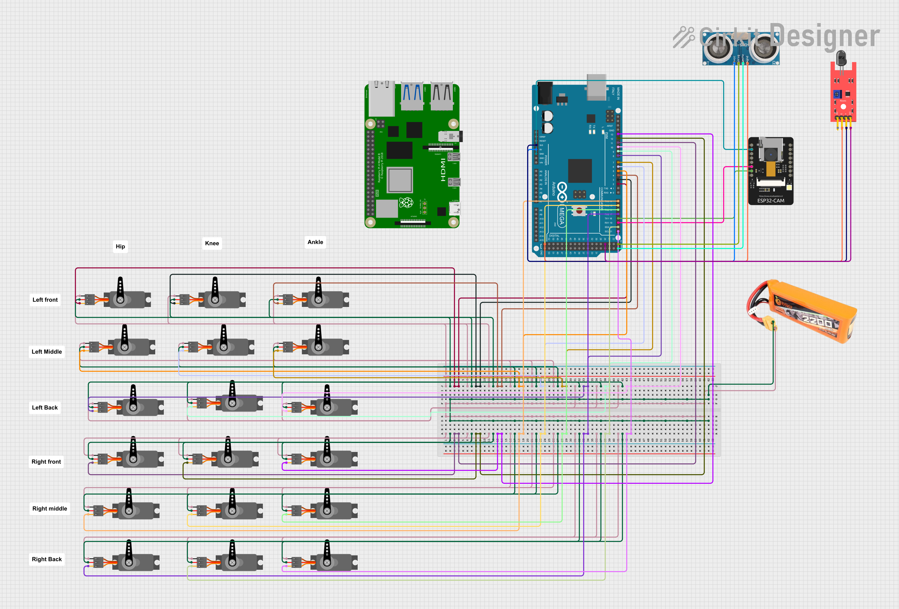
This circuit involves an Arduino Mega 2560 microcontroller, an ESP32-CAM module, multiple servo motors, a LiPo battery, a Raspberry Pi 4B, an ultrasonic sensor, and a KY-026 flame sensor. The Arduino Mega 2560 serves as the main controller, interfacing with the servos, sensors, and the ESP32-CAM. The LiPo battery powers the servos, while the Arduino and sensors are powered through their respective power pins.
Component List
Arduino Mega 2560
- Description: A microcontroller board based on the ATmega2560.
- Pins: IOREF, RESET, 3V3, 5V, GND, VIN, A0-A15, D0-D53, AREF, SDA, SCL
ESP32-CAM
- Description: A small camera module with an ESP32-S chip.
- Pins: 5V, GND, IO12, IO13, IO15, IO14, IO2, IO4, VOT, VOR, VCC, IO0, IO16, 3V3
Servo Motors
- Description: Standard servo motors.
- Pins: GND, VCC, PWM
LiPo Battery 2200mAH 30C
- Description: A rechargeable lithium polymer battery.
- Pins: VCC, GND
Raspberry Pi 4B
- Description: A small single-board computer.
- Pins: 3V3, 5V, GPIO2-GPIO27, ID_SD, ID_SC, TR01_TAP, TR00_TAP, TR03_TAP, TR02_TAP, RUN, GLOBAL_EN, ETH, HDMI 0, HDMI 1, CAMERA, AV
Ultrasonic Sensor
- Description: A sensor used to measure distance.
- Pins: +VCC, Trigger, Echo, GND
KY-026 Flame Sensor
- Description: A sensor used to detect flame.
- Pins: A0, GND, VCC, D0
Wiring Details
Arduino Mega 2560
- 3V3: Connected to KY-026 Flame Sensor VCC
- 5V: Connected to Ultrasonic Sensor +VCC, Trigger, Echo
- GND: Connected to ESP32-CAM GND, KY-026 Flame Sensor GND, Ultrasonic Sensor GND
- D2 PWM: Connected to Servo PWM
- D3 PWM: Connected to Servo PWM
- D4 PWM: Connected to Servo PWM
- D5 PWM: Connected to Servo PWM
- D6 PWM: Connected to Servo PWM
- D7 PWM: Connected to Servo PWM
- D8 PWM: Connected to Servo PWM
- D9 PWM: Connected to Servo PWM
- D10 PWM: Connected to Servo PWM
- D11 PWM: Connected to Servo PWM
- D12 PWM: Connected to Servo PWM
- D13 PWM: Connected to Servo PWM
- D14/TX3: Connected to Servo PWM
- D15/RX3: Connected to Servo PWM
- D16 PWM/TX2: Connected to Servo PWM
- D17 PWM/RX2: Connected to Servo PWM
- D18/TX1: Connected to ESP32-CAM IO2
- D19/RX1: Connected to ESP32-CAM IO14
- D20/SDA: Connected to Servo PWM
- D21/SCL: Connected to Servo PWM
- D26: Connected to KY-026 Flame Sensor D0
ESP32-CAM
- GND: Connected to Arduino Mega 2560 GND
- IO2: Connected to Arduino Mega 2560 D18/TX1
- IO14: Connected to Arduino Mega 2560 D19/RX1
Servo Motors
- GND: Connected to LiPo Battery GND
- VCC: Connected to LiPo Battery VCC
- PWM: Connected to various PWM pins on Arduino Mega 2560
LiPo Battery 2200mAH 30C
- GND: Connected to Servo GND
- VCC: Connected to Servo VCC
Ultrasonic Sensor
- +VCC: Connected to Arduino Mega 2560 5V
- Trigger: Connected to Arduino Mega 2560 5V
- Echo: Connected to Arduino Mega 2560 5V
- GND: Connected to Arduino Mega 2560 GND
KY-026 Flame Sensor
- VCC: Connected to Arduino Mega 2560 3V3
- GND: Connected to Arduino Mega 2560 GND
- D0: Connected to Arduino Mega 2560 D26
Documented Code
Arduino Mega 2560 Code (sketch.ino)
void setup() {
  // put your setup code here, to run once:

}

void loop() {
  // put your main code here, to run repeatedly:

}
Additional Documentation (documentation.txt)
This documentation provides a comprehensive overview of the circuit, including a summary, detailed component list, wiring details, and the code used in the microcontroller.