Cirkit Designer
Your all-in-one circuit design IDE
Home /
Project Documentation
Arduino UNO Controlled Blinking LED Circuit
Circuit Documentation
Summary of the Circuit
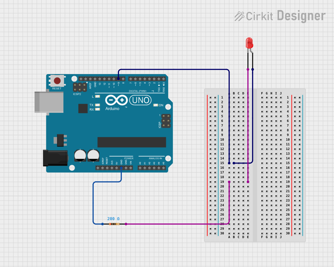
This circuit consists of an Arduino UNO microcontroller, a red two-pin LED, and a resistor. The purpose of the circuit is to blink the LED on and off at a one-second interval. The Arduino UNO is programmed to provide a digital output signal that alternates between high and low states, driving the LED through a current-limiting resistor.
Component List
Arduino UNO
- Description: A microcontroller board based on the ATmega328P.
- Pins Used: D9, GND
- Purpose: Acts as the control unit for blinking the LED.
LED: Two Pin (red)
- Description: A basic red light-emitting diode.
- Pins: Cathode, Anode
- Purpose: Emits light when powered.
Resistor
- Description: A passive two-terminal electrical component that implements electrical resistance as a circuit element.
- Resistance: 200 Ohms
- Purpose: Limits the current flowing through the LED to prevent damage.
Wiring Details
Arduino UNO
- D9 connected to the Anode of the LED.
- GND connected to Pin1 of the Resistor.
LED: Two Pin (red)
- Anode connected to D9 of the Arduino UNO.
- Cathode connected to Pin2 of the Resistor.
Resistor
- Pin1 connected to GND of the Arduino UNO.
- Pin2 connected to the Cathode of the LED.
Documented Code
// Define the pin for the LED
const int ledPin = 9;

void setup() {
  // Set the LED pin as an OUTPUT
  pinMode(ledPin, OUTPUT);
}

void loop() {
  // Turn the LED on
  digitalWrite(ledPin, HIGH);
  // Wait for 1 second
  delay(1000);
  // Turn the LED off
  digitalWrite(ledPin, LOW);
  // Wait for 1 second
  delay(1000);
}
Filename: sketch.ino
Code Description
The code is written for the Arduino UNO microcontroller. It defines the LED pin as digital pin 9 and sets it as an output in the setup() function. The loop() function turns the LED on by setting the pin high, waits for one second, turns the LED off by setting the pin low, and then waits for another second. This cycle repeats indefinitely, causing the LED to blink.