
Arduino UNO-Based Health Monitoring System with GSM and LCD Display
View and Edit Project In Cirkit Designer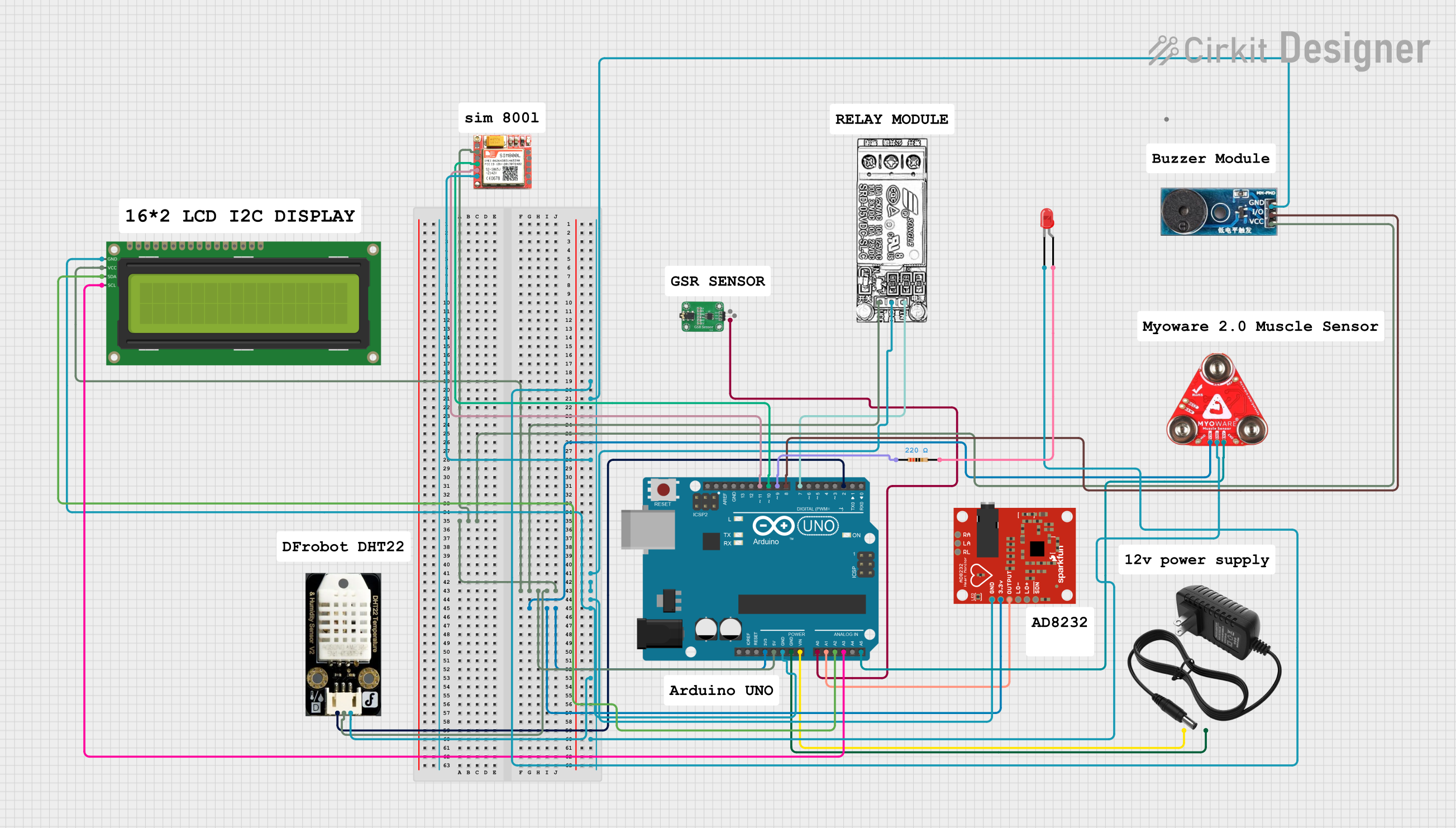
Circuit Documentation
Summary
This circuit is designed to monitor various physiological parameters using multiple sensors and display the data on an LCD screen. It also includes a GSM module for sending SMS alerts and a relay module to control a steam generator. The circuit is built around an Arduino UNO microcontroller, which reads data from the sensors and controls the output devices.
Component List
Arduino UNO
- Description: Microcontroller board based on the ATmega328P.
- Pins: UNUSED, IOREF, Reset, 3.3V, 5V, GND, Vin, A0, A1, A2, A3, A4, A5, SCL, SDA, AREF, D13, D12, D11, D10, D9, D8, D7, D6, D5, D4, D3, D2, D1, D0
GSR Sensor
- Description: Measures Galvanic Skin Response.
- Pins: GND, VCC, OUT
AD8232 HeartRate Monitor
- Description: Measures heart rate.
- Pins: GND, 3.3v, OUTPUT, LO-, LO+, SDN, RA, LA, RL
DFrobot DHT22 Temperature & Humidity Sensor V2
- Description: Measures temperature and humidity.
- Pins: Signal, VCC, GND
16x2 I2C LCD
- Description: Displays data on a 16x2 character LCD.
- Pins: GND, VCC, SDA, SCL
SIM 800L
- Description: GSM module for sending SMS.
- Pins: NFT, RING, VCC, DTR, RST, MIC +, RXD, MIC-, TXD, SPK+, GND, SPK-
12V Power Supply
- Description: Provides 12V power to the circuit.
- Pins: +, -
Myoware 2.0 Muscle Sensor
- Description: Measures muscle activity.
- Pins: VIN, GND, ENV
Relay Module
- Description: Controls high voltage devices.
- Pins: NC, COM, INPUT, GND, VCC
Buzzer Module
- Description: Emits sound for alerts.
- Pins: GND, Vcc, I/O
LED: Two Pin (red)
- Description: Indicates status with light.
- Pins: cathode, anode
Resistor
- Description: Limits current flow.
- Pins: pin1, pin2
- Properties: Resistance: 220 Ohms
Wiring Details
Arduino UNO
5V connected to:
- VCC of SIM 800L
- VCC of DFrobot DHT22 Temperature & Humidity Sensor V2
- Vcc of Buzzer Module
- VCC of 16x2 I2C LCD
- VCC of Relay Module
3.3V connected to:
- VIN of Myoware 2.0 Muscle Sensor
- 3.3v of AD8232 HeartRate Monitor
GND connected to:
- cathode of LED: Two Pin (red)
- GND of Buzzer Module
- GND of SIM 800L
- GND of Relay Module
- GND of AD8232 HeartRate Monitor
- GND of 16x2 I2C LCD
- GND of DFrobot DHT22 Temperature & Humidity Sensor V2
- GND of Myoware 2.0 Muscle Sensor
-
- of 12V Power Supply
Vin connected to:
-
- of 12V Power Supply
-
A0 connected to:
- OUT of GSR Sensor
A1 connected to:
- OUTPUT of AD8232 HeartRate Monitor
A2 connected to:
- SDA of 16x2 I2C LCD
A3 connected to:
- SCL of 16x2 I2C LCD
A5 connected to:
- ENV of Myoware 2.0 Muscle Sensor
D11 connected to:
- TXD of SIM 800L
D10 connected to:
- RXD of SIM 800L
D9 connected to:
- pin1 of Resistor
D8 connected to:
- I/O of Buzzer Module
D7 connected to:
- INPUT of Relay Module
D2 connected to:
- Signal of DFrobot DHT22 Temperature & Humidity Sensor V2
GND connected to:
-
- of 12V Power Supply
-
GSR Sensor
- OUT connected to:
- A0 of Arduino UNO
AD8232 HeartRate Monitor
- OUTPUT connected to:
- A1 of Arduino UNO
DFrobot DHT22 Temperature & Humidity Sensor V2
- Signal connected to:
- D2 of Arduino UNO
16x2 I2C LCD
SDA connected to:
- A2 of Arduino UNO
SCL connected to:
- A3 of Arduino UNO
Myoware 2.0 Muscle Sensor
- ENV connected to:
- A5 of Arduino UNO
SIM 800L
TXD connected to:
- D11 of Arduino UNO
RXD connected to:
- D10 of Arduino UNO
Resistor
pin1 connected to:
- D9 of Arduino UNO
pin2 connected to:
- anode of LED: Two Pin (red)
Buzzer Module
- I/O connected to:
- D8 of Arduino UNO
Relay Module
- INPUT connected to:
- D7 of Arduino UNO
12V Power Supply
+ connected to:
- Vin of Arduino UNO
- connected to:
- GND of Arduino UNO
Code Documentation
#include <DHT.h>
#include <LiquidCrystal_I2C.h>
#include <SoftwareSerial.h>

// Pin Definitions
const int gsrPin = A0;         // GSR Sensor
const int ecgPin = A1;         // ECG Sensor
const int dhtPin = 2;          // DHT22
const int emgPin = A5;         // EMG Sensor
const int relayPin = 7;        // Relay for steam generator
const int buzzerPin = 8;       // Buzzer
const int ledPin = 9;          // Red LED

// GSM Module Pins
SoftwareSerial gsmSerial(10, 11); // RX, TX

// DHT Sensor Initialization
DHT dht(dhtPin, DHT22);

// LCD Display Initialization
LiquidCrystal_I2C lcd(0x27, 16, 2);

// Timing Variables
unsigned long startTime;
const unsigned long maxDuration = 20 * 60 * 1000; // 20 minutes
const unsigned long alertTime = 15 * 60 * 1000;   // 15 minutes

void setup() {
  Serial.begin(9600);
  gsmSerial.begin(9600);
  dht.begin();
  pinMode(relayPin, OUTPUT);
  pinMode(buzzerPin, OUTPUT);
  pinMode(ledPin, OUTPUT);
  digitalWrite(relayPin, LOW); // Turn off steam generator
  digitalWrite(buzzerPin, LOW); // Turn off buzzer
  digitalWrite(ledPin, LOW);    // Turn off LED
  lcd.begin(16, 2); // Initialize the LCD with 16 columns and 2 rows
  lcd.backlight();
  startTime = millis();
}

void loop() {
  unsigned long currentTime = millis();
  if (currentTime - startTime >= maxDuration) {
    digitalWrite(relayPin, LOW); // Turn off steam generator
    return; // Stop the loop after 20 minutes
  }
  if (currentTime - startTime >= alertTime) {
    digitalWrite(buzzerPin, HIGH); // Turn on buzzer
  }
  // Read Sensors
  int gsrValue = analogRead(gsrPin);
  int ecgValue = analogRead(ecgPin);
  float temperature = dht.readTemperature();
  int emgValue = analogRead(emgPin); // Read EMG sensor
  // Control Steam Generator based on Temperature
  if (temperature < 40) {
    digitalWrite(relayPin, HIGH); // Turn on steam generator
  } else if (temperature > 46) {
    digitalWrite(relayPin, LOW);  // Turn off steam generator
  }
  // Stop steam generator if hydration exceeds limit
  if (gsrValue > 600) { // Example threshold
    digitalWrite(relayPin, LOW); // Turn off steam generator
    digitalWrite(buzzerPin, HIGH