
Arduino UNO Controlled Weighing System with GLCD Interface and Dual Stepper Motor Drivers
View and Edit Project In Cirkit Designer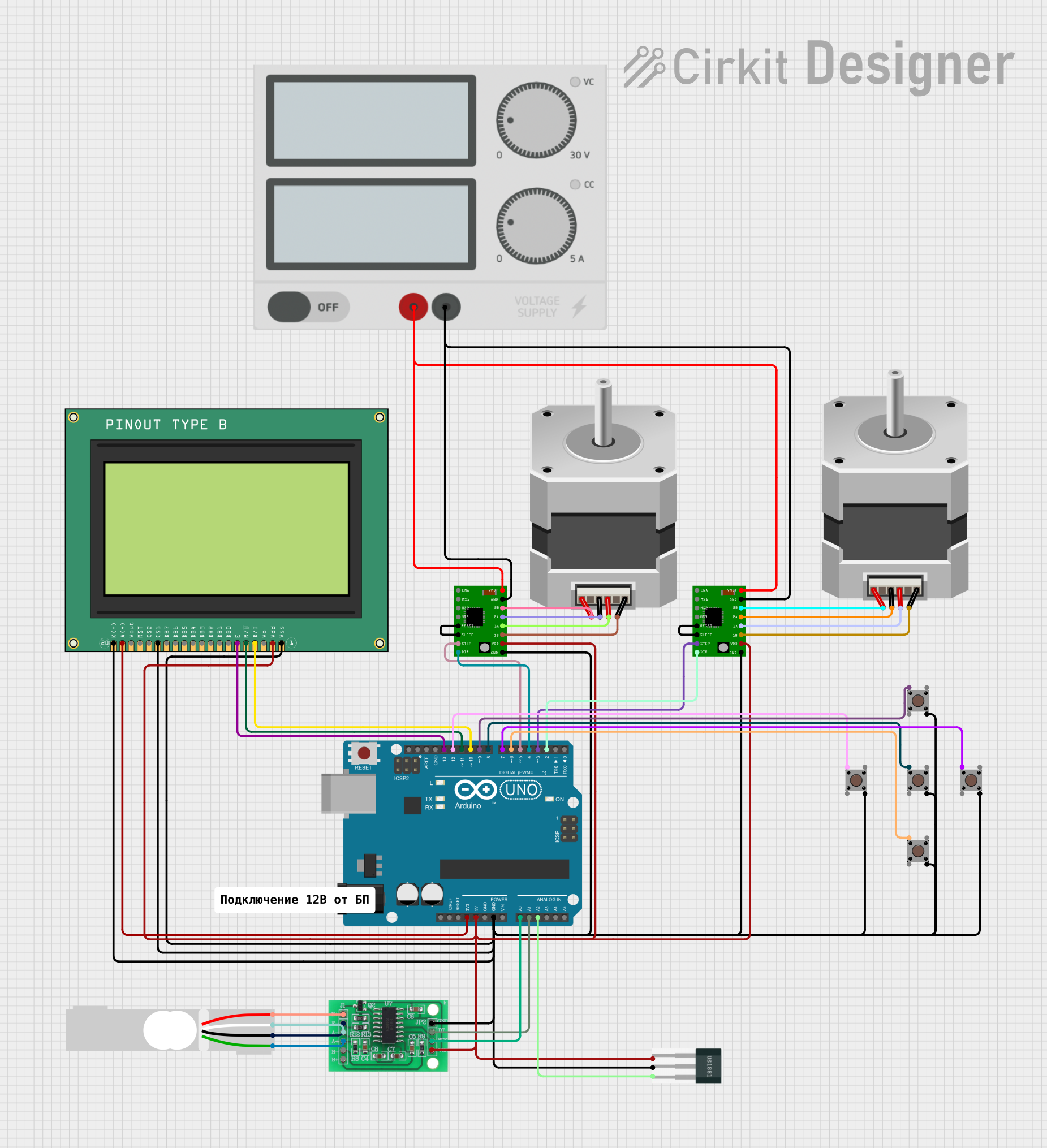
Circuit Documentation
Summary
This circuit integrates various components including an Arduino UNO, HX711 bridge sensor interface, load cell, hall sensor, multiple pushbuttons, a graphic LCD display, two A4988 stepper motor driver carriers, two bipolar stepper motors, and a power supply. The Arduino UNO serves as the central microcontroller, interfacing with sensors, controlling the LCD display, and managing the stepper motor drivers. The HX711 interfaces with the load cell to measure weight, while the hall sensor detects magnetic fields. Pushbuttons provide user input, and the graphic LCD display offers a visual interface. The A4988 drivers control the stepper motors, which could be used for precise positioning in applications such as 3D printers or CNC machines. The power supply provides the necessary voltage and current to the system.
Component List
Arduino UNO
- Microcontroller board based on the ATmega328P
- Provides digital and analog I/O pins
- Can be powered via USB or an external power source
HX711 - Bridge Sensor Interface
- 24-bit analog-to-digital converter (ADC) designed for weigh scales and industrial control applications
- Interfaces with load cells
Load Cell - Red/white/black/green
- Transducer that converts force into an electrical signal
- Used in conjunction with the HX711 for weight measurement
Hall Sensor
- Sensor that detects magnetic fields
- Outputs a voltage corresponding to the magnetic field strength
Pushbutton (5 instances)
- Simple switch mechanism for user input
- Normally open, closes the circuit when pressed
Graphic LCD Display (GLCD 128x64)
- Monochrome graphic display with a resolution of 128x64 pixels
- Used for displaying text, graphics, and user interface elements
A4988 Stepper Motor Driver Carrier (2 instances)
- Module for driving bipolar stepper motors
- Supports microstepping for precise control
Stepper Motor (Bipolar) (2 instances)
- Motor that moves in discrete steps
- Used for precise control of position and speed
Power Supply
- Provides regulated voltage and current to the circuit
- Essential for powering the components safely
Wiring Details
Arduino UNO
3.3Vconnected to GLCD 128x64 pin19 A(+)5Vconnected to A4988 Stepper Motor Driver CarrierVCC, GLCD 128x642 Vdd, Hall Sensor-, and HX7113.3/3.5V SupplyGNDconnected to various components including Pushbuttons, A4988 Stepper Motor Driver Carriers, GLCD 128x64, Hall Sensor, and HX711A0connected to HX711SCK - CLOCK (IN)A1connected to HX711DATA (OUT)A2connected to Hall SensorSD13connected to GLCD 128x646 EnableD12,D9,D8,D7,D6connected to PushbuttonsD5,D4connected to A4988 Stepper Motor Driver CarrierSTEPandDIRfor the first motorD3,D2connected to A4988 Stepper Motor Driver CarrierSTEPandDIRfor the second motor
HX711 - Bridge Sensor Interface
E+,E-,A-,A+connected to corresponding Load Cell pins
Load Cell - Red/white/black/green
- Interfaced with HX711 for weight measurement
Hall Sensor
Sconnected to Arduino UNOA2+and-connected to power supply lines
Pushbuttons
- One side of each pushbutton connected to Arduino UNO digital pins
D12,D9,D8,D7,D6 - Other side of each pushbutton connected to ground
Graphic LCD Display (GLCD 128x64)
19 A(+)and20 K(-)connected to Arduino UNO3.3VandGNDrespectively- Control pins connected to various Arduino UNO digital pins
A4988 Stepper Motor Driver Carrier
VCCandGNDconnected to power supply linesSTEPandDIRconnected to Arduino UNO digital pins for control1A,1B,2A,2Bconnected to corresponding Stepper Motor pinsRESETandSLEEPshorted together for each driver
Stepper Motor (Bipolar)
- Connected to corresponding A4988 Stepper Motor Driver Carrier pins
Power Supply
+and-connected to various components requiring power
Documented Code
Arduino UNO - sketch.ino
void setup() {
  // put your setup code here, to run once:

}

void loop() {
  // put your main code here, to run repeatedly:

}
Arduino UNO - documentation.txt
(No additional documentation provided)
This concludes the documentation for the provided circuit design.