
ESP8266 NodeMCU Controlled Relay with AC Bulb and Opto-isolated Input
View and Edit Project In Cirkit Designer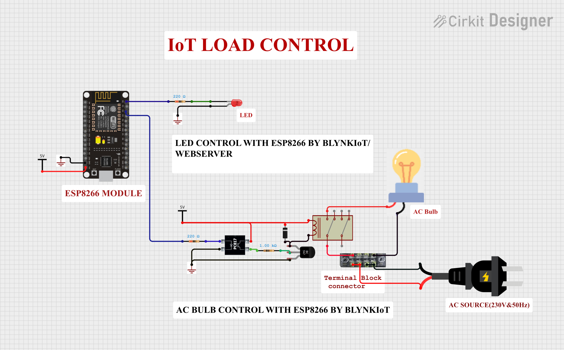
Circuit Documentation
Summary
The circuit described by the provided inputs is a control circuit that utilizes an ESP8266 NodeMCU microcontroller to drive an LED and a relay, which in turn controls an AC-powered bulb. The circuit includes protection and control elements such as resistors, a diode, a PC817 optocoupler, and a BC547 transistor. The NodeMCU is powered by a Vcc source, and the ground connections are distributed across the components. The relay is used to switch the AC source to the bulb, and the optocoupler isolates the microcontroller from the relay control circuit.
Component List
Microcontroller
- ESP8266 NodeMCU: A Wi-Fi capable microcontroller with multiple GPIO pins.
Passive Components
- Resistors: Three resistors with different resistance values are used for current limiting and voltage division.
- Two resistors with a resistance of 220 Ohms.
- One resistor with a resistance of 1000 Ohms.
- LED (Red): A two-pin red LED used as an indicator.
Power Supply Components
- Vcc: A power supply input for the circuit.
- GND: Ground reference points for the circuit.
Control and Protection Components
- PC817 Optocoupler: An optocoupler used for electrical isolation between the microcontroller and the relay control circuit.
- BC547 Transistor: An NPN transistor used to amplify the current for driving the relay.
- Diode: A diode used for flyback protection in the relay circuit.
Output Components
- Relay: An electromechanical switch used to control the AC-powered bulb.
- Bulb: An AC-powered bulb that is the load in the circuit.
Connection Components
- Terminal Block: A terminal block used for connecting the AC source to the relay and the bulb.
Power Source
- AC Source: An alternating current power source for the bulb.
Wiring Details
ESP8266 NodeMCU
- D0 connected to a 220 Ohm resistor.
- D2 connected to a 220 Ohm resistor.
- GND connected to the ground reference.
- VIN connected to the Vcc power supply.
LED (Red)
- Cathode connected to a 220 Ohm resistor and ground.
- Anode connected to the ground reference.
Resistors
- Two 220 Ohm resistors connected between the ESP8266 NodeMCU and the LED, and the ESP8266 NodeMCU and the optocoupler, respectively.
- One 1000 Ohm resistor connected between the optocoupler and the BC547 transistor.
PC817 Optocoupler
- Anode connected to a 220 Ohm resistor.
- Cathode connected to the ground reference and the emitter of the BC547 transistor.
- Collector connected to the relay coil and the cathode of the diode.
- Emitter connected to a 1000 Ohm resistor.
BC547 Transistor
- Collector connected to the relay coil and the anode of the diode.
- Base connected to a 1000 Ohm resistor.
- Emitter connected to the cathode of the optocoupler and the ground reference.
Diode
- Cathode connected to the collector of the optocoupler.
- Anode connected to the relay coil and the collector of the BC547 transistor.
Relay
- Coil connected to the collector of the optocoupler and the collector of the BC547 transistor.
- Common 1 connected to the terminal block.
- NO 1 connected to the bulb.
Bulb
- Power connected to the NO 1 contact of the relay.
- GND connected to the terminal block.
Terminal Block
- Pins 1 and 3 connected to the negative side of the AC source.
- Pins 5 and 7 connected to the positive side of the AC source.
- Pin 2 connected to the bulb.
- Pin 8 connected to the common contact of the relay.
AC Source
- Positive connected to the terminal block.
- Negative connected to the terminal block.
Documented Code
No code was provided for the microcontroller. The operation of the circuit is assumed to be controlled by the firmware running on the ESP8266 NodeMCU, which would handle GPIO pin manipulation to turn the LED on or off and to control the relay for powering the bulb. Without the code, the specific logic and functionality cannot be documented.