Cirkit Designer
Your all-in-one circuit design IDE
Home /
Project Documentation
Arduino-Based Water Quality Monitoring System with PH and Temperature Sensors
Circuit Documentation
Summary
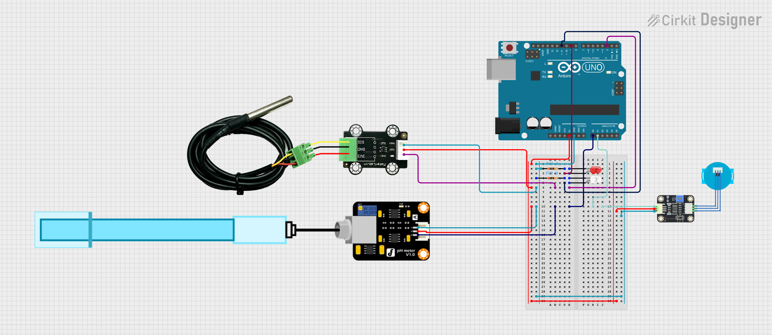
This circuit is designed to measure pH levels and temperature while also monitoring turbidity. It utilizes an Arduino UNO as the main microcontroller to interface with a pH meter, a temperature sensor, and a turbidity sensor. Additionally, it includes two LEDs for visual indication of the system's status.
Component List
PH Meter
- Description: A sensor used to measure the pH level of a solution.
- Pins: Signal, VCC, GND
MKE-S15 DS18B20 Waterproof Temperature Sensor
- Description: A waterproof temperature sensor that provides accurate temperature readings.
- Pins: SIG, 5V, GND
Arduino UNO
- Description: A microcontroller board based on the ATmega328P, used for programming and controlling the circuit.
- Pins: Various digital and analog pins for input/output operations.
Resistor (200 Ohm)
- Description: A passive electrical component that limits the flow of current in the circuit.
- Pins: pin1, pin2
LED: Two Pin (red)
- Description: A red LED used for visual indication.
- Pins: cathode, anode
LED: Two Pin (white)
- Description: A white LED used for visual indication.
- Pins: cathode, anode
Turbidity Sensor
- Description: A sensor that measures the turbidity of a liquid, indicating the presence of suspended particles.
- Pins: OUT, VCC, GND
Wiring Details
PH Meter
- Signal connected to A0 on Arduino UNO
- VCC connected to 5V on Arduino UNO
- GND connected to GND on Arduino UNO
MKE-S15 DS18B20 Waterproof Temperature Sensor
- SIG connected to D2 on Arduino UNO
- 5V connected to 5V on Arduino UNO
- GND connected to GND on Arduino UNO
Turbidity Sensor
- OUT connected to A1 on Arduino UNO
- VCC connected to 5V on Arduino UNO
- GND connected to GND on Arduino UNO
LED: Two Pin (red)
- anode connected to D9 on Arduino UNO
- cathode connected to pin2 of the first resistor
Resistor (200 Ohm)
- pin1 connected to GND on Arduino UNO
- pin2 connected to cathode of the red LED
LED: Two Pin (white)
- anode connected to D11 on Arduino UNO
- cathode connected to pin2 of the second resistor
Resistor (200 Ohm)
- pin1 connected to GND on Arduino UNO
- pin2 connected to cathode of the white LED
Documented Code
Arduino UNO Code
void setup() {
  // put your setup code here, to run once:

}

void loop() {
  // put your main code here, to run repeatedly:

}
Documentation
This section is reserved for additional documentation or notes related to the circuit and its operation. Currently, there are no additional notes provided.