Cirkit Designer
Your all-in-one circuit design IDE
Home /
Project Documentation
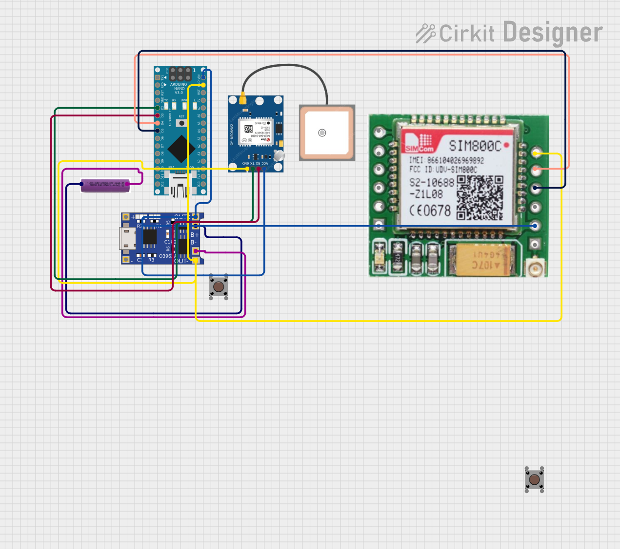
Arduino Nano GPS Tracker with GSM Module and Battery Power
Circuit Documentation
Summary
This circuit interfaces an Arduino Nano with a GPS NEO 6M module and a SIM800c GSM module. The GPS module provides location data, which is then transmitted via the GSM module. The circuit is powered by a 3.7V battery, which is managed by a TP4056 charging module.
Component List
Arduino Nano
- Description: A small, complete, and breadboard-friendly board based on the ATmega328P.
- Pins: D1/TX, D0/RX, RESET, GND, D2, D3, D4, D5, D6, D7, D8, D9, D10, D11/MOSI, D12/MISO, VIN, 5V, A7, A6, A5, A4, A3, A2, A1, A0, AREF, 3V3, D13/SCK
GPS NEO 6M
- Description: A GPS module that provides location data.
- Pins: VCC, RX, TX, GND
SIM800c GSM Module
- Description: A GSM module used for sending and receiving SMS and data.
- Pins: SPK-, SPK+, MIC-, MIC+, DTR, RING, GND, TXD, RXD, LINK GND, ANT, VCC(3.7 - 4.2)
TP4056
- Description: A lithium battery charger module.
- Pins: OUT-, B-, B+, OUT+, IN-, IN+
3.7V Battery
- Description: A rechargeable lithium battery.
- Pins: +, -
Pushbutton (x2)
- Description: A simple pushbutton switch.
- Pins: Pin 3 (out), Pin 4 (out), Pin 1 (in), Pin 2 (in)
Wiring Details
Arduino Nano
- D2 connected to TX of GPS NEO 6M
- D3 connected to RX of GPS NEO 6M
- D4 connected to TXD of SIM800c GSM Module
- D5 connected to RXD of SIM800c GSM Module
- VIN connected to OUT+ of TP4056
- GND connected to OUT- of TP4056
GPS NEO 6M
- TX connected to D2 of Arduino Nano
- RX connected to D3 of Arduino Nano
- VCC connected to OUT+ of TP4056
- GND connected to OUT- of TP4056
SIM800c GSM Module
- TXD connected to D4 of Arduino Nano
- RXD connected to D5 of Arduino Nano
- VCC(3.7 - 4.2) connected to OUT+ of TP4056
- GND connected to OUT- of TP4056
TP4056
- OUT+ connected to VIN of Arduino Nano, VCC of GPS NEO 6M, and VCC(3.7 - 4.2) of SIM800c GSM Module
- OUT- connected to GND of Arduino Nano, GND of GPS NEO 6M, and GND of SIM800c GSM Module
- B+ connected to + of 3.7V Battery
- B- connected to - of 3.7V Battery
3.7V Battery
- + connected to B+ of TP4056
- - connected to B- of TP4056
Pushbutton (x2)
- Not connected in the provided net list.
Code Documentation
/*
 * Arduino Nano GPS and GSM Module Interface
 *
 * This code reads GPS data from the NEO 6M module and sends it via the
 * SIM800c GSM module. The GPS module is connected to pins D2 (TX) and D3 (RX)
 * of the Arduino Nano. The GSM module is connected to pins D4 (TXD) and D5 (RXD).
 */

#include <SoftwareSerial.h>

// GPS module connections
#define GPS_TX_PIN 2
#define GPS_RX_PIN 3

// GSM module connections
#define GSM_TX_PIN 4
#define GSM_RX_PIN 5

SoftwareSerial gpsSerial(GPS_TX_PIN, GPS_RX_PIN); // RX, TX
SoftwareSerial gsmSerial(GSM_TX_PIN, GSM_RX_PIN); // RX, TX

void setup() {
  // Initialize serial communication
  Serial.begin(9600);
  gpsSerial.begin(9600);
  gsmSerial.begin(9600);

  // Wait for GSM module to initialize
  delay(1000);
  Serial.println("GSM Module Initialized");
}

void loop() {
  // Read data from GPS module
  if (gpsSerial.available()) {
    String gpsData = gpsSerial.readString();
    Serial.println("GPS Data: " + gpsData);

    // Send GPS data via GSM module
    gsmSerial.println(gpsData);
    Serial.println("Data sent via GSM");
  }

  // Small delay to avoid flooding
  delay(1000);
}
This code initializes the GPS and GSM modules and continuously reads GPS data, which is then sent via the GSM module. The GPS module is connected to pins D2 (TX) and D3 (RX) of the Arduino Nano, while the GSM module is connected to pins D4 (TXD) and D5 (RXD).