
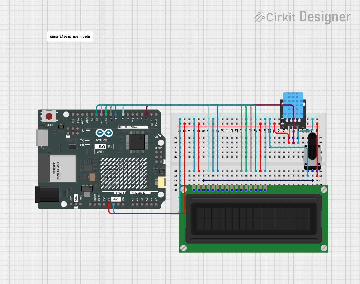
Circuit Documentation
Summary
The circuit in question is designed to interface an Arduino UNO R4 WiFi microcontroller with a DHT11 temperature and humidity sensor and an LCD display. The LCD is used to display the temperature and humidity readings obtained from the DHT11 sensor. A rotary potentiometer is included to adjust the contrast of the LCD display. The Arduino board manages the sensor data acquisition and controls the LCD display to update the readings periodically.
Component List
DHT11
- Description: A basic, low-cost digital temperature and humidity sensor.
- Pins:
5V: Power supply (5V)S: Signal output to microcontrollerGND: Ground
LCD Display (16 pin)
- Description: A 16x2 character LCD display that shows alphanumeric characters.
- Pins:
VSS: Ground for the LCDVDD: Power supply for the LCD (5V)VO: Contrast adjustmentRS: Register SelectR_W: Read/Write (grounded for write only)E: Enable pinDB0-DB7: Data lines (DB4-DB7 used for 4-bit mode)A: Anode for backlightK: Cathode for backlight
Arduino UNO R4 WiFi
- Description: A microcontroller board based on the ATmega328 with integrated WiFi.
- Pins:
GND: Ground5V: Power supply (5V)D0-D13: Digital I/O pinsA0-A5: Analog input pinsRESET: Reset pin- Other pins not used in this circuit
Rotary Potentiometer
- Description: A three-terminal resistor with a rotating contact that forms an adjustable voltage divider.
- Pins:
leg1: Typically connected to a power sourcewiper: The adjustable output voltage (connected toVOon the LCD)leg2: Typically connected to ground
- Properties:
Resistance: 10,000 Ohms
Wiring Details
DHT11
5Vto Arduino5VSto ArduinoD2GNDto common ground
LCD Display (16 pin)
VSS,R_W,Kto common groundVDD,Ato Arduino5VVOto wiper of Rotary PotentiometerRSto ArduinoD7Eto ArduinoD8DB4to ArduinoD9DB5to ArduinoD10DB6to ArduinoD11DB7to ArduinoD12
Rotary Potentiometer
leg1to Arduino5VwipertoVOon the LCDleg2to common ground
Arduino UNO R4 WiFi
GNDto common ground5Vto power components requiring 5V- Digital pins
D2,D7,D8,D9,D10,D11,D12to respective components as detailed above
Documented Code
#include <DHT.h>
#include <LiquidCrystal.h>

// Initialize DHT sensor
#define DHTPIN 2     // DHT11 data pin connected to D2
#define DHTTYPE DHT11
DHT dht(DHTPIN, DHTTYPE);

// Initialize the LCD
const int rs = 7, en = 8, d4 = 9, d5 = 10, d6 = 11, d7 = 12;
LiquidCrystal lcd(rs, en, d4, d5, d6, d7);

void setup() {
  // Start the DHT sensor
  dht.begin();

  // Start the LCD
  lcd.begin(16, 2);
  lcd.print("Temp: ");
  lcd.setCursor(0, 1);
  lcd.print("Humidity: ");
}

void loop() {
  // Read temperature and humidity
  float h = dht.readHumidity();
  float t = dht.readTemperature();

  // Check if any reads failed and exit early (to try again).
  if (isnan(h) || isnan(t)) {
    lcd.setCursor(6, 0);
    lcd.print("Error");
    lcd.setCursor(10, 1);
    lcd.print("Error");
    return;
  }

  // Print temperature and humidity to LCD
  lcd.setCursor(6, 0);
  lcd.print(t);
  lcd.print(" C");
  lcd.setCursor(10, 1);
  lcd.print(h);
  lcd.print(" %");

  // Wait a few seconds between measurements.
  delay(2000);
}
This code initializes the DHT11 sensor and the LCD display, then enters a loop where it reads temperature and humidity from the DHT11 sensor and displays the values on the LCD. If the sensor fails to provide valid readings, an error message is displayed instead.