Cirkit Designer
Your all-in-one circuit design IDE
Home /
Project Documentation
Arduino Mega 2560 Controlled Servo System with RFID and LCD Interface
Circuit Documentation
Summary
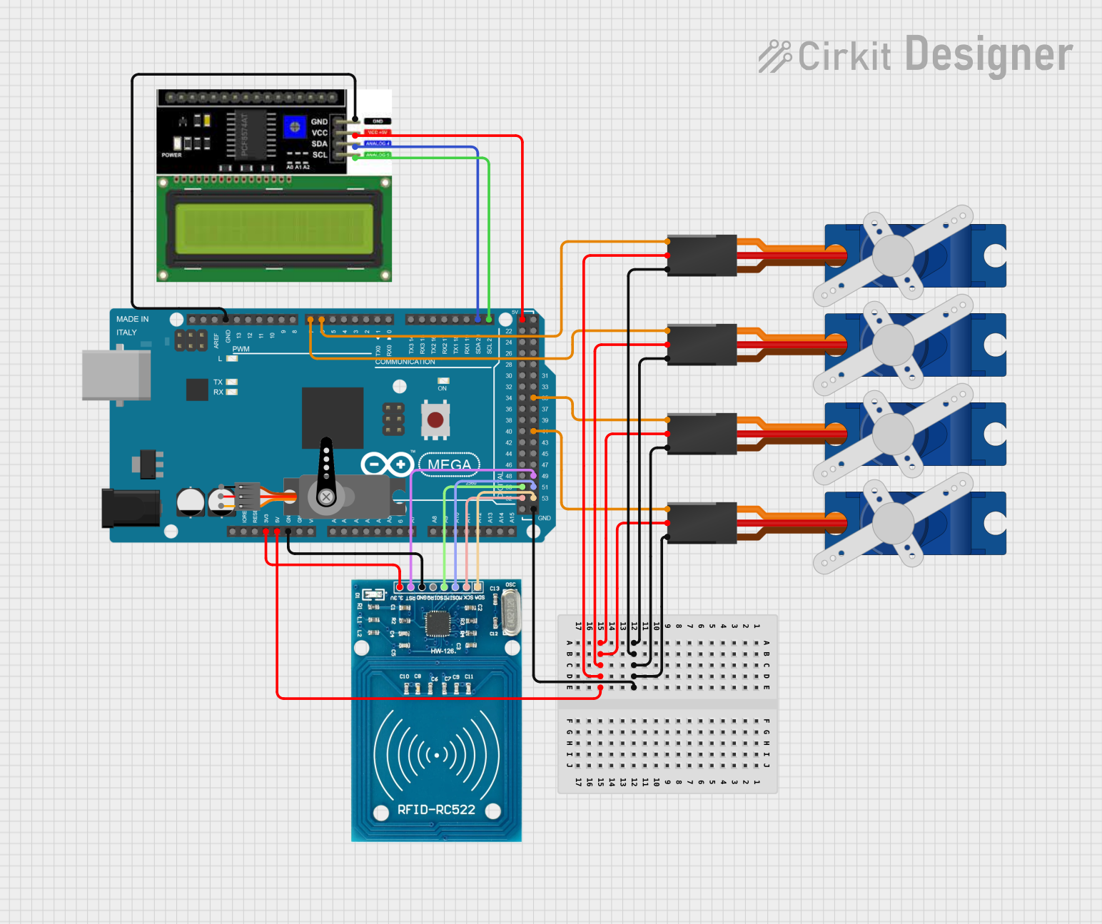
This circuit integrates an Arduino Mega 2560 microcontroller with multiple peripherals including servos, an LCD I2C display, and an RFID-RC522 module. The servos are controlled via PWM signals from the Arduino, while the LCD display communicates over the I2C bus. The RFID-RC522 module interfaces with the Arduino through SPI communication for RFID reading capabilities.
Component List
Arduino Mega 2560
- Microcontroller board based on the ATmega2560
- Offers 54 digital input/output pins (of which 15 can be used as PWM outputs), 16 analog inputs, 4 UARTs (hardware serial ports), a 16 MHz crystal oscillator, a USB connection, a power jack, an ICSP header, and a reset button.
Servo (Generic)
- An actuator that can be precisely controlled for angular or linear position, velocity, and acceleration.
- Typically has three connections: power (VCC), ground (GND), and control (PWM).
Tower Pro SG90 Servo
- A small and lightweight servo motor capable of precise position control.
- Operates on +5V and uses a single control wire for PWM signal.
LCD I2C Display
- A liquid crystal display that communicates via the I2C bus protocol.
- Requires power (VCC), ground (GND), and two I2C lines (SDA for data, SCL for clock).
RFID-RC522
- An RFID reader/writer module that operates at 13.56 MHz.
- Interfaces with microcontrollers via SPI and requires power (VCC), ground (GND), reset (RST), and SPI lines (MISO, MOSI, SCK, SDA).
Wiring Details
Arduino Mega 2560
- GND: Connected to the ground pins of all Tower Pro SG90 servos, the LCD I2C display, and the RFID-RC522 module.
- 5V: Powers all Tower Pro SG90 servos and the LCD I2C display.
- 3V3: Powers the RFID-RC522 module.
- D21/SCL: Connected to the SCL pin of the LCD I2C display.
- D20/SDA: Connected to the SDA pin of the LCD I2C display.
- D6 PWM: Controls the signal pin of one Tower Pro SG90 servo.
- D7 PWM: Controls the signal pin of another Tower Pro SG90 servo.
- D41: Controls the signal pin of another Tower Pro SG90 servo.
- D35: Controls the signal pin of another Tower Pro SG90 servo.
- D52: Connected to the SCK pin of the RFID-RC522 module.
- D50: Connected to the MISO pin of the RFID-RC522 module.
- D53: Connected to the SDA pin of the RFID-RC522 module.
- D51: Connected to the MOSI pin of the RFID-RC522 module.
- D49: Connected to the RST pin of the RFID-RC522 module.
Tower Pro SG90 Servo
- GND: Connected to the ground (GND) on the Arduino Mega 2560.
- +5V: Powered by the 5V output from the Arduino Mega 2560.
- Signal: Controlled by a PWM output from the Arduino Mega 2560 (D6, D7, D41, or D35).
LCD I2C Display
- GND: Connected to the ground (GND) on the Arduino Mega 2560.
- VCC: Powered by the 5V output from the Arduino Mega 2560.
- SDA: Connected to the D20/SDA pin on the Arduino Mega 2560.
- SCL: Connected to the D21/SCL pin on the Arduino Mega 2560.
RFID-RC522
- VCC (3.3V): Powered by the 3.3V output from the Arduino Mega 2560.
- RST: Connected to the D49 pin on the Arduino Mega 2560.
- GND: Connected to the ground (GND) on the Arduino Mega 2560.
- IRQ: Not connected in this circuit.
- MISO: Connected to the D50 pin on the Arduino Mega 2560.
- MOSI: Connected to the D51 pin on the Arduino Mega 2560.
- SCK: Connected to the D52 pin on the Arduino Mega 2560.
- SDA: Connected to the D53 pin on the Arduino Mega 2560.
Documented Code
Arduino Mega 2560 - sketch.ino
void setup() {
  // put your setup code here, to run once:

}

void loop() {
  // put your main code here, to run repeatedly:

}
Arduino Mega 2560 - documentation.txt
(No additional documentation provided)