Cirkit Designer
Your all-in-one circuit design IDE
Home /
Project Documentation
Arduino Mega 2560 and ESP8266 Wi-Fi Controlled Robotic Car with Ultrasonic Sensor
Circuit Documentation
Summary
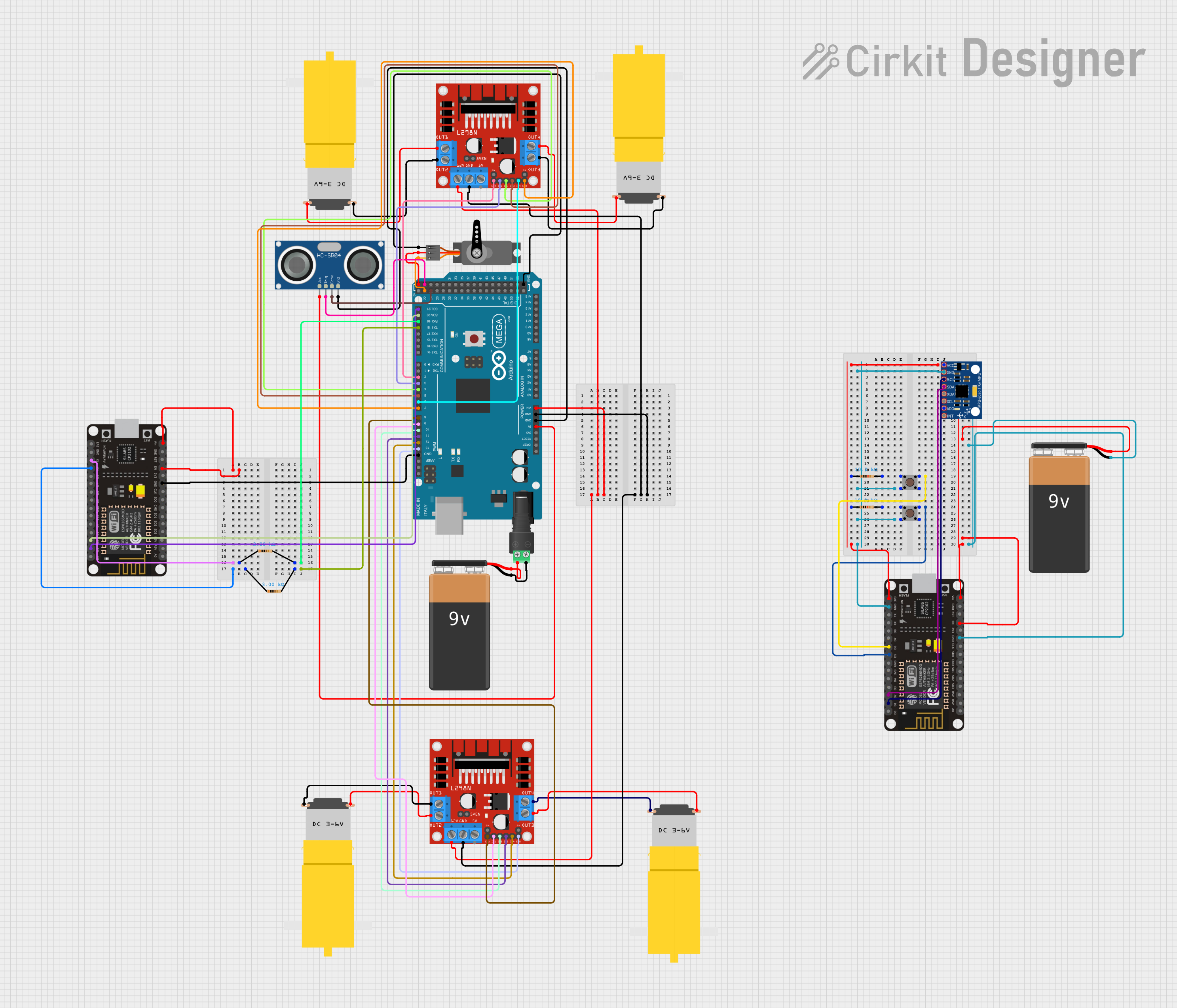
This document provides a detailed overview of a circuit involving an Arduino Mega 2560, L298N DC motor drivers, hobby motors, a servo, an ultrasonic sensor, an ESP8266 NodeMCU, an MPU-6050, pushbuttons, resistors, and a 9V battery. The circuit is designed to control multiple motors and sensors, with communication facilitated by the Arduino Mega 2560 and ESP8266 NodeMCU.
Component List
Arduino Mega 2560
- Description: A microcontroller board based on the ATmega2560.
- Pins: IOREF, RESET, 3V3, 5V, GND, VIN, A0-A15, D0-D53, AREF, SDA, SCL
L298N DC Motor Driver
- Description: A dual H-Bridge motor driver.
- Pins: OUT1, OUT2, 12V, GND, 5V, OUT3, OUT4, 5V-ENA-JMP-I, 5V-ENA-JMP-O, +5V-J1, +5V-J2, ENA, IN1, IN2, IN3, IN4, ENB
Motor Amarillo Motorreductor Hobby
- Description: A small DC motor with a gearbox.
- Pins: vcc, GND
Servo
- Description: A small servo motor.
- Pins: GND, VCC, PWM
HC-SR04 Ultrasonic Sensor
- Description: An ultrasonic distance sensor.
- Pins: VCC, TRIG, ECHO, GND
ESP8266 NodeMCU
- Description: A low-cost Wi-Fi microchip with full TCP/IP stack and microcontroller capability.
- Pins: D0-D8, RX, TX, A0, RSV, SD3, SD2, SD1, CMD, SD0, CLK, EN, RST, VIN, 3V3, GND
MPU-6050
- Description: A 6-axis motion tracking device.
- Pins: VCC, GND, SCL, SDA, XDA, XCL, AD0, INT
9V Battery
- Description: A standard 9V battery.
- Pins: -, +
2.1mm Barrel Jack with Terminal Block
- Description: A barrel jack for power connections.
- Pins: POS, NEG
Resistor
- Description: A passive electrical component with resistance.
- Pins: pin1, pin2
- Properties: Resistance: 3000 Ohms, 10000 Ohms
Pushbutton
- Description: A simple pushbutton switch.
- Pins: Pin 1 (in), Pin 2 (in), Pin 3 (out), Pin 4 (out)
Wiring Details
Arduino Mega 2560
- VIN: Connected to 12V of both L298N DC motor drivers.
- GND: Connected to GND of both L298N DC motor drivers, HC-SR04 Ultrasonic Sensor, ESP8266 NodeMCU, and Servo.
- 5V: Connected to VCC of HC-SR04 Ultrasonic Sensor and Servo.
- D21/SCL: Connected to D1 of ESP8266 NodeMCU.
- D20/SDA: Connected to D2 of ESP8266 NodeMCU.
- D19/RX1: Connected to pin2 of a 3000 Ohm resistor.
- D18/TX1: Connected to pin2 of another 3000 Ohm resistor.
- D2 PWM: Connected to ENA of the first L298N DC motor driver.
- D3 PWM: Connected to IN1 of the first L298N DC motor driver.
- D4 PWM: Connected to IN2 of the first L298N DC motor driver.
- D5 PWM: Connected to IN3 of the first L298N DC motor driver.
- D6 PWM: Connected to IN4 of the first L298N DC motor driver.
- D7 PWM: Connected to ENB of the first L298N DC motor driver.
- D8 PWM: Connected to ENA of the second L298N DC motor driver.
- D9 PWM: Connected to IN1 of the second L298N DC motor driver.
- D10 PWM: Connected to IN2 of the second L298N DC motor driver.
- D11 PWM: Connected to IN3 of the second L298N DC motor driver.
- D12 PWM: Connected to IN4 of the second L298N DC motor driver.
- D13 PWM: Connected to ENB of the second L298N DC motor driver.
- D24: Connected to ECHO of HC-SR04 Ultrasonic Sensor.
- D22: Connected to PWM of Servo.
- D23: Connected to TRIG of HC-SR04 Ultrasonic Sensor.
L298N DC Motor Driver (First)
- 12V: Connected to VIN of Arduino Mega 2560.
- GND: Connected to GND of Arduino Mega 2560.
- OUT1: Connected to vcc of the first hobby motor.
- OUT2: Connected to GND of the first hobby motor.
- OUT3: Connected to GND of the second hobby motor.
- OUT4: Connected to vcc of the second hobby motor.
L298N DC Motor Driver (Second)
- 12V: Connected to VIN of Arduino Mega 2560.
- GND: Connected to GND of Arduino Mega 2560.
- OUT1: Connected to GND of the third hobby motor.
- OUT2: Connected to vcc of the third hobby motor.
- OUT3: Connected to vcc of the fourth hobby motor.
- OUT4: Connected to GND of the fourth hobby motor.
HC-SR04 Ultrasonic Sensor
- VCC: Connected to 5V of Arduino Mega 2560.
- GND: Connected to GND of Arduino Mega 2560.
- TRIG: Connected to D23 of Arduino Mega 2560.
- ECHO: Connected to D24 of Arduino Mega 2560.
ESP8266 NodeMCU
- D1: Connected to D21/SCL of Arduino Mega 2560.
- D2: Connected to D20/SDA of Arduino Mega 2560.
- GND: Connected to GND of Arduino Mega 2560.
- RX: Connected to pin1 of a 3000 Ohm resistor.
- TX: Connected to pin1 of another 3000 Ohm resistor.
- EN: Connected to VIN of ESP8266 NodeMCU.
- VIN: Connected to EN of ESP8266 NodeMCU.
MPU-6050
- SCL: Connected to D1 of the second ESP8266 NodeMCU.
- SDA: Connected to D2 of the second ESP8266 NodeMCU.
- GND: Connected to GND of the second ESP8266 NodeMCU.
- VCC: Connected to 3V3 of the second ESP8266 NodeMCU.
Pushbutton
- Pin 4 (out): Connected to D5 of the second ESP8266 NodeMCU.
- Pin 4 (out): Connected to D6 of the second ESP8266 NodeMCU.
- Pin 3 (out): Connected to pin2 of a 10000 Ohm resistor.
- Pin 3 (out): Connected to pin2 of another 10000 Ohm resistor.
- Pin 1 (in): Connected to Pin 1 (in) of another pushbutton.
9V Battery
- -: Connected to GND of the second ESP8266 NodeMCU.
- +: Connected to VIN of the second ESP8266 NodeMCU.
2.1mm Barrel Jack with Terminal Block
- NEG: Connected to - of the first 9V Battery.
- POS: Connected to + of the first 9V Battery.
Resistor
- pin1: Connected to RX of the first ESP8266 NodeMCU.
- pin1: Connected to TX of the first ESP8266 NodeMCU.
- pin1: Connected to 3V3 of the second ESP8266 NodeMCU.
- pin1: Connected to VCC of MPU-6050.
- pin2: Connected to D19/RX1 of Arduino Mega 2560.
- pin2: Connected to D18/TX1 of Arduino Mega 2560.
- pin2: Connected to Pin 3 (out) of the first pushbutton.
- pin2: Connected to Pin 3 (out) of the second pushbutton.
Documented Code
Arduino Mega 2560 Code
void setup() {
  // put your setup code here, to run once:

}

void loop() {
  // put your main code here, to run repeatedly:

}
ESP8266 NodeMCU Code
// No code provided for this microcontroller.
This document provides a comprehensive overview of the circuit, including a summary, component list, wiring details, and documented code.