
Arduino UNO and L293D Motor Driver-Based Battery-Powered Dual Motor Control with Hall Sensors and LED Indicators
View and Edit Project In Cirkit Designer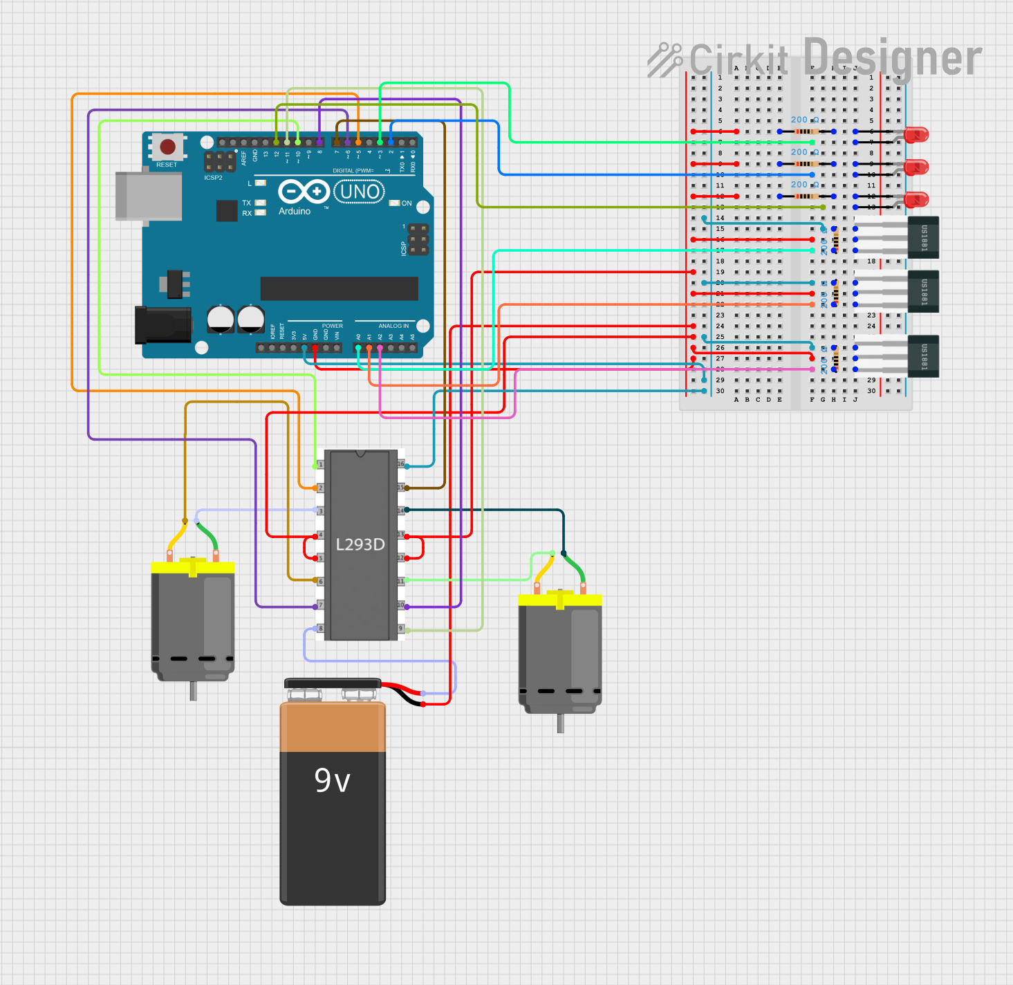
Circuit Documentation
Summary
This circuit is designed to control two DC motors and three LEDs using an Arduino UNO microcontroller. The circuit also includes three Hall sensors to detect magnetic fields and control the motors and LEDs accordingly. The L293D motor driver is used to drive the DC motors, and resistors are used to limit the current through the LEDs and Hall sensors. A 9V battery powers the entire circuit.
Component List
Arduino UNO
- Description: Microcontroller board based on the ATmega328P.
- Pins: UNUSED, IOREF, Reset, 3.3V, 5V, GND, Vin, A0, A1, A2, A3, A4, A5, SCL, SDA, AREF, D13, D12, D11, D10, D9, D8, D7, D6, D5, D4, D3, D2, D1, D0
L293D Motor Driver
- Description: Dual H-Bridge motor driver IC.
- Pins: enable 1, input 1, output 1, gnd, output 2, input 2, vs, vss, input 4, output 4, output 3, input 3, enable 2
DC Motor
- Description: Standard DC motor.
- Pins: pin 1, pin 2
9V Battery
- Description: Power source for the circuit.
- Pins: -, +
LED: Two Pin (red)
- Description: Red LED.
- Pins: cathode, anode
Resistor
- Description: Resistor with a resistance of 200 Ohms.
- Pins: pin1, pin2
Hall Sensor
- Description: Sensor to detect magnetic fields.
- Pins: -, +, S
Wiring Details
Arduino UNO
GND is connected to:
- GND of L293D Motor Driver
- GND of 9V Battery
- GND of Hall Sensors
- GND of Resistors
5V is connected to:
- VSS of L293D Motor Driver
-
- of Hall Sensors
D3 is connected to:
- Anode of LED 1
D2 is connected to:
- Anode of LED 2
D12 is connected to:
- Anode of LED 3
A0 is connected to:
- S of Hall Sensor 1
- Pin1 of Resistor 1
A1 is connected to:
- S of Hall Sensor 2
- Pin1 of Resistor 2
A2 is connected to:
- S of Hall Sensor 3
- Pin1 of Resistor 3
D10 is connected to:
- Enable 1 of L293D Motor Driver
D5 is connected to:
- Input 1 of L293D Motor Driver
D6 is connected to:
- Input 2 of L293D Motor Driver
D7 is connected to:
- Input 4 of L293D Motor Driver
D8 is connected to:
- Input 3 of L293D Motor Driver
D11 is connected to:
- Enable 2 of L293D Motor Driver
L293D Motor Driver
GND is connected to:
- GND of Arduino UNO
- GND of 9V Battery
VSS is connected to:
- 5V of Arduino UNO
VS is connected to:
-
- of 9V Battery
-
Output 1 is connected to:
- Pin 1 of DC Motor 1
Output 2 is connected to:
- Pin 2 of DC Motor 1
Output 3 is connected to:
- Pin 2 of DC Motor 2
Output 4 is connected to:
- Pin 1 of DC Motor 2
DC Motor 1
Pin 1 is connected to:
- Output 1 of L293D Motor Driver
Pin 2 is connected to:
- Output 2 of L293D Motor Driver
DC Motor 2
Pin 1 is connected to:
- Output 4 of L293D Motor Driver
Pin 2 is connected to:
- Output 3 of L293D Motor Driver
9V Battery
- is connected to:
- GND of Arduino UNO
- GND of L293D Motor Driver
+ is connected to:
- VS of L293D Motor Driver
LED 1
Anode is connected to:
- D3 of Arduino UNO
Cathode is connected to:
- Pin2 of Resistor 1
LED 2
Anode is connected to:
- D2 of Arduino UNO
Cathode is connected to:
- Pin2 of Resistor 2
LED 3
Anode is connected to:
- D12 of Arduino UNO
Cathode is connected to:
- Pin2 of Resistor 3
Resistor 1
Pin1 is connected to:
- S of Hall Sensor 1
- A0 of Arduino UNO
Pin2 is connected to:
- Cathode of LED 1
Resistor 2
Pin1 is connected to:
- S of Hall Sensor 2
- A1 of Arduino UNO
Pin2 is connected to:
- Cathode of LED 2
Resistor 3
Pin1 is connected to:
- S of Hall Sensor 3
- A2 of Arduino UNO
Pin2 is connected to:
- Cathode of LED 3
Hall Sensor 1
+ is connected to:
- 5V of Arduino UNO
- is connected to:
- GND of Arduino UNO
S is connected to:
- Pin1 of Resistor 1
- A0 of Arduino UNO
Hall Sensor 2
+ is connected to:
- 5V of Arduino UNO
- is connected to:
- GND of Arduino UNO
S is connected to:
- Pin1 of Resistor 2
- A1 of Arduino UNO
Hall Sensor 3
+ is connected to:
- 5V of Arduino UNO
- is connected to:
- GND of Arduino UNO
S is connected to:
- Pin1 of Resistor 3
- A2 of Arduino UNO
Code Documentation
Arduino UNO Code
const int hallSensor1 = A0;
const int hallSensor2 = A1;
const int hallSensor3 = A2;
const int motor1Pin1 = 5;
const int motor1Pin2 = 6;
const int motor2Pin1 = 7;
const int motor2Pin2 = 8;
const int led1Pin = 3;
const int led2Pin = 2;
const int led3Pin = 12;

void setup() {
  pinMode(hallSensor1, INPUT);
  pinMode(hallSensor2, INPUT);
  pinMode(hallSensor3, INPUT);
  pinMode(motor1Pin1, OUTPUT);
  pinMode(motor1Pin2, OUTPUT);
  pinMode(motor2Pin1, OUTPUT);
  pinMode(motor2Pin2, OUTPUT);
  pinMode(led1Pin, OUTPUT);
  pinMode(led2Pin, OUTPUT);
  pinMode(led3Pin, OUTPUT);
}

void loop() {
  int sensor1Value = digitalRead(hallSensor1);
  int sensor2Value = digitalRead(hallSensor2);
  int sensor3Value = digitalRead(hallSensor3);

  digitalWrite(led1Pin, sensor1Value == HIGH ? HIGH : LOW);
  digitalWrite(led2Pin, sensor2Value == HIGH ? HIGH : LOW);
  digitalWrite(led3Pin, sensor3Value == HIGH ? HIGH : LOW);

  if (sensor1Value == HIGH) {
    digitalWrite(motor1Pin1, HIGH);
    digitalWrite(motor1Pin2, LOW);
  } else {
    digitalWrite(motor1Pin1, LOW);
    digitalWrite(motor1Pin2, LOW);
  }

  if (sensor2Value == HIGH) {
    digitalWrite(motor2Pin1, HIGH);
    digitalWrite(motor2Pin2, LOW);
  } else {
    digitalWrite(motor2Pin1, LOW);
    digitalWrite(motor2Pin2, LOW);
  }

  if (sensor3Value == HIGH) {
    digitalWrite(motor1Pin1, LOW);
    digitalWrite(motor1Pin2, HIGH);
  }
}