
Arduino UNO-Based Security System with Flame Sensor, PIR, and Reed Switch
View and Edit Project In Cirkit Designer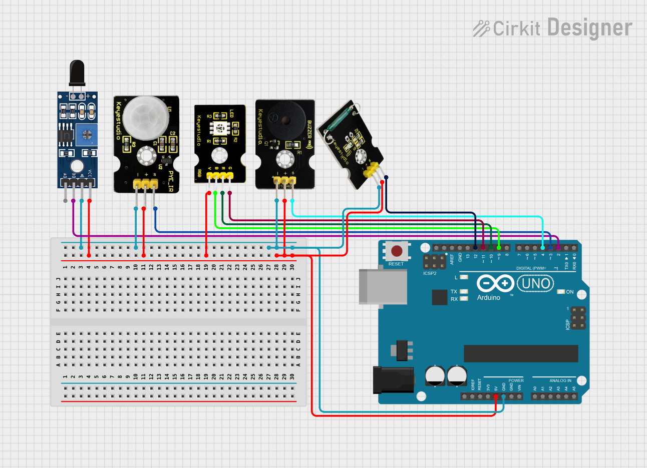
Circuit Documentation
Summary
The circuit in question is designed to interface an Arduino UNO with a variety of sensors and output devices, including a flame sensor (Sensor SHT113 Flame), a PIR (Passive Infrared) sensor, an RGB LED, a buzzer, and a reed switch. The Arduino UNO serves as the central microcontroller unit, processing inputs from the sensors and controlling the output devices based on the programmed logic. The circuit is powered by a 5V supply, which is distributed to the components that require it. Ground connections are also distributed to all components to complete the electrical paths.
Component List
Arduino UNO
- Description: A microcontroller board based on the ATmega328P.
- Purpose: Acts as the central processing unit for the circuit, reading sensor inputs and controlling outputs.
Sensor SHT113 Flame
- Description: A flame detection sensor module.
- Purpose: Detects the presence of a flame or fire and provides a digital output signal.
PIR Sensor
- Description: A motion detection sensor using infrared.
- Purpose: Detects motion within its field of view and provides a digital output signal.
RGB LED
- Description: A light-emitting diode that can emit red, green, and blue colors.
- Purpose: Provides visual feedback or signaling based on the circuit's state.
Buzzer
- Description: An electronic buzzer capable of producing sound.
- Purpose: Emits an audible alert or signal.
Reed Switch
- Description: A magnetic field-activated switch.
- Purpose: Detects the presence of a magnetic field and provides a digital output signal.
Wiring Details
Arduino UNO
- 5V: Connected to the 5V power supply line.
- GND: Connected to the ground line.
- D12: Connected to the reed switch signal pin.
- D11: Connected to the RGB LED green pin.
- D10: Connected to the RGB LED red pin.
- D9: Connected to the RGB LED blue pin.
- D4: Connected to the buzzer signal pin.
- D3: Connected to the PIR sensor data pin.
- D2: Connected to the flame sensor digital output pin.
Sensor SHT113 Flame
- VCC: Connected to the 5V power supply line.
- GND: Connected to the ground line.
- D0: Connected to Arduino UNO pin D2.
PIR Sensor
- VCC: Connected to the 5V power supply line.
- GND: Connected to the ground line.
- Data: Connected to Arduino UNO pin D3.
RGB LED
- 5V: Connected to the 5V power supply line.
- G: Connected to Arduino UNO pin D11.
- R: Connected to Arduino UNO pin D10.
- B: Connected to Arduino UNO pin D9.
Buzzer
- 5V: Connected to the 5V power supply line.
- GND: Connected to the ground line.
- S: Connected to Arduino UNO pin D4.
Reed Switch
- 5V: Connected to the 5V power supply line.
- GND: Connected to the ground line.
- S: Connected to Arduino UNO pin D12.
Documented Code
Arduino UNO Code (sketch.ino)
void setup() {
  // put your setup code here, to run once:

}

void loop() {
  // put your main code here, to run repeatedly:

}
Note: The provided code is a template and does not contain any functional logic. It needs to be populated with the appropriate setup and loop code to control the circuit based on the desired behavior.