
ESP8266 NodeMCU Controlled Smart Irrigation and Security System
View and Edit Project In Cirkit Designer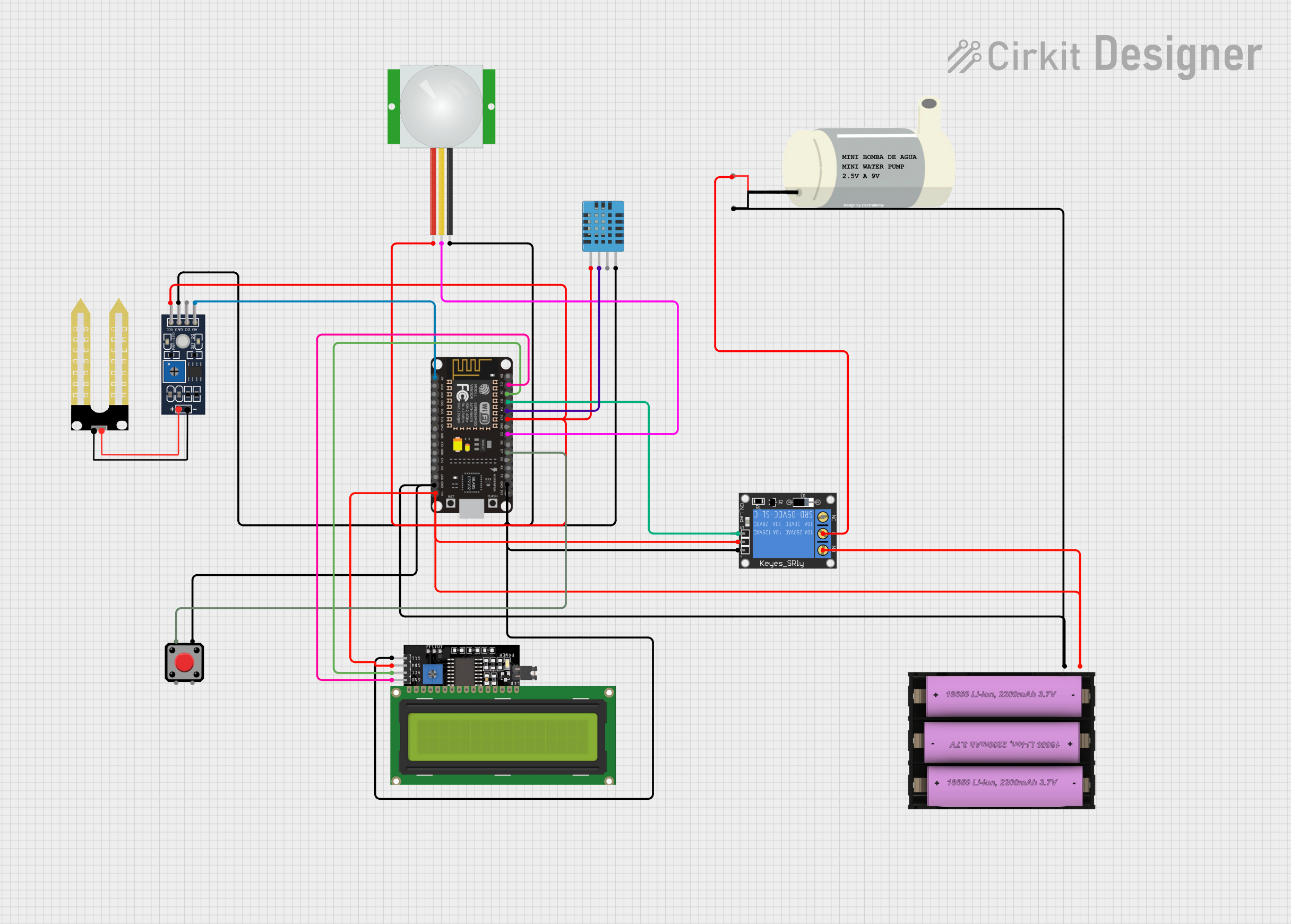
Circuit Documentation
Summary
This circuit is designed to interface various sensors and actuators with an ESP8266 NodeMCU microcontroller. The system is capable of reading environmental data, detecting motion, and controlling a relay which in turn can control a water pump. The ESP8266 NodeMCU is also connected to an LCD display for real-time feedback of sensor data and system status. The circuit is powered by a 7V battery set.
Component List
1-Channel Relay (5V 10A)
- Description: A relay module capable of switching up to 10A loads.
- Purpose: To control the Mini Water Pump.
Set battery (7V)
- Description: A power source for the circuit.
- Purpose: To provide the necessary voltage for the circuit components.
PIR Sensor
- Description: A motion detection sensor.
- Purpose: To detect the presence of motion in the environment.
Mini Water Pump
- Description: A pump for moving water.
- Purpose: To pump water when activated by the relay.
DHT11 Humidity and Temperature Sensor
- Description: A sensor for measuring temperature and humidity.
- Purpose: To monitor environmental conditions.
LCD Display 16x4 I2C
- Description: An LCD display with I2C communication.
- Purpose: To display sensor readings and system status.
Humidity YL-69
- Description: A soil moisture sensor.
- Purpose: To measure the moisture level of the soil.
Pushbutton
- Description: A simple pushbutton switch.
- Purpose: To provide a manual control interface.
ESP8266 NodeMCU
- Description: A Wi-Fi capable microcontroller with digital and analog I/O.
- Purpose: To process sensor data, control actuators, and communicate with external devices.
Wiring Details
1-Channel Relay (5V 10A)
- Signal: Connected to ESP8266 NodeMCU D3
- Power: Connected to Set battery (7V) positive terminal
- Ground: Connected to common ground
- Normally Open (NO): Connected to Mini Water Pump VCC
- Common (C): Connected to Mini Water Pump GND
Set battery (7V)
- Positive (+): Connected to ESP8266 NodeMCU VIN, LCD Display 16x4 I2C VCC, and 1-Channel Relay power
- Negative (-): Connected to common ground
PIR Sensor
- VDD: Connected to common 3.3V rail
- SIG: Connected to ESP8266 NodeMCU D5
- GND: Connected to common ground
Mini Water Pump
- VCC: Connected to 1-Channel Relay NO
- GND: Connected to 1-Channel Relay C
DHT11 Humidity and Temperature Sensor
- VDD: Connected to common 3.3V rail
- DATA: Connected to ESP8266 NodeMCU D4
- GND: Connected to common ground
LCD Display 16x4 I2C
- SCL: Connected to ESP8266 NodeMCU D1
- SDA: Connected to ESP8266 NodeMCU D2
- VCC: Connected to Set battery (7V) positive terminal
- GND: Connected to common ground
Humidity YL-69
- A0: Connected to ESP8266 NodeMCU A0
- D0: Not connected
- GND: Connected to common ground
- VCC: Connected to common 3.3V rail
Pushbutton
- Pin 1: Connected to ESP8266 NodeMCU D7
- Pin 2, Pin 3, Pin 4: Not connected
ESP8266 NodeMCU
- D1 (SCL): Connected to LCD Display 16x4 I2C SCL
- D2 (SDA): Connected to LCD Display 16x4 I2C SDA
- D3: Connected to 1-Channel Relay signal
- D4: Connected to DHT11 DATA
- D5: Connected to PIR SIG
- D7: Connected to Pushbutton Pin 1
- A0: Connected to Humidity YL-69 A0
- 3V3: Connected to common 3.3V rail
- GND: Connected to common ground
- VIN: Connected to Set battery (7V) positive terminal
Documented Code
ESP8266 NodeMCU (Main Controller)
// Pin Definitions
#define RELAY_PIN_1       D3   // Relay
#define PUSH_BUTTON_1     D7   // Button
#define SOIL_SENSOR_PIN   A0   // Soil Moisture Sensor
#define PIR_SENSOR_PIN    D5   // PIR Motion Sensor
#define DHT_SENSOR_PIN    D4   // DHT11 Temperature Sensor

// Include the library files
#include <LiquidCrystal_I2C.h>
#include <ESP8266WiFi.h>
#include <BlynkSimpleEsp8266.h>
#include <DHT.h>

// Initialize the LCD display
LiquidCrystal_I2C lcd(0x3F, 16, 2);

// Blynk credentials and WiFi credentials
char auth[] = "YourAuthToken";  // Enter your Blynk Auth token
char ssid[] = "YourSSID";       // Enter your WIFI SSID
char pass[] = "YourPassword";   // Enter your WIFI Password

// Initialize DHT sensor
DHT dht(DHT_SENSOR_PIN, DHT11);

// Blynk timer for scheduling
BlynkTimer timer;

// Variables to store sensor data
int relay1State = LOW;
int pushButton1State = HIGH;
int PIR_ToggleValue;

// Function prototypes
void checkPhysicalButton();
void DHT11sensor();
void soilMoistureSensor();
void PIRsensor();

void setup() {
  Serial.begin(9600);
  lcd.begin();
  lcd.backlight();
  pinMode(PIR_SENSOR_PIN, INPUT);
  pinMode(RELAY_PIN_1, OUTPUT);
  digitalWrite(RELAY_PIN_1, LOW);
  pinMode(PUSH_BUTTON_1, INPUT_PULLUP);
  Blynk.begin(auth, ssid, pass, "blynk.cloud", 80);
  dht.begin();
  lcd.setCursor(0, 0);
  lcd.print("  Initializing  ");
  // Initialization sequence
  for (int a = 5; a <= 10; a++) {
    lcd.setCursor(a, 1);
    lcd.print(".");
    delay(500);
  }
  lcd.clear();
  lcd.setCursor(11, 1);
  lcd.print("W:OFF");
  // Schedule functions
  timer.setInterval(100L, soilMoistureSensor);
  timer.setInterval(100L, DHT11sensor);
  timer.setInterval(500L, checkPhysicalButton);
}

void loop() {
  if (PIR_ToggleValue == 1) {
    lcd.setCursor(5, 1);
    lcd.print("M:ON ");
    PIRsensor();
  } else {
    lcd.setCursor(5, 1);
    lcd.print("M:OFF");
    WidgetLED LED(V5);
    LED.off();
  }

  if (relay1State == HIGH) {
    lcd.setCursor(11, 1);
    lcd.print("W:ON ");
  } else {
    lcd.setCursor(11, 1);
    lcd.print("W:OFF");
  }

  Blynk.run();  // Run the Blynk library
  timer.run();  // Run the Blynk timer
}

// Function to read and display DHT11 sensor values
void DHT11sensor() {
  float h = dht.readHumidity();
  float t = dht.readTemperature();
  if (isnan(h) || isnan(t)) {
    Serial.println("Failed to read from DHT sensor!");
    return;
  }
  Blynk.virtualWrite(V0, t);
  Blynk.virtualWrite(V1, h);
  lcd.setCursor(0, 0);
  lcd.print("T:");
  lcd.print(t);
  lcd.setCursor(8, 0);
  lcd.print("H:");
  lcd.print(h);
}

// Function to read and display soil moisture values
void soilMoistureSensor() {
  int value = analogRead(SOIL_SENSOR_PIN);
  value = map(value, 0, 1024, 0, 100);
  value = (value - 100) * -1;
  Blynk.virtualWrite(V3, value);
  lcd.setCursor(0, 1);
  lcd.print("S:");
  lcd.print(value);
  lcd.print(" ");
}

// Function to read PIR sensor values and trigger events
void PIRsensor() {
  bool value = digitalRead(PIR_SENSOR_PIN);
  if (value) {
    Blynk.logEvent("pirmotion", "WARNING! Motion Detected!");
    WidgetLED LED(V5);
    LED.on();
  } else {
    WidgetLED LED(V5);
    LED.off();
  }
}

// Blynk function to handle virtual pin writes
BLYNK_WRITE(V6) {
  PIR_ToggleValue = param.asInt();
}

// Sync virtual pin state with