
Circuit Documentation
Summary of the Circuit
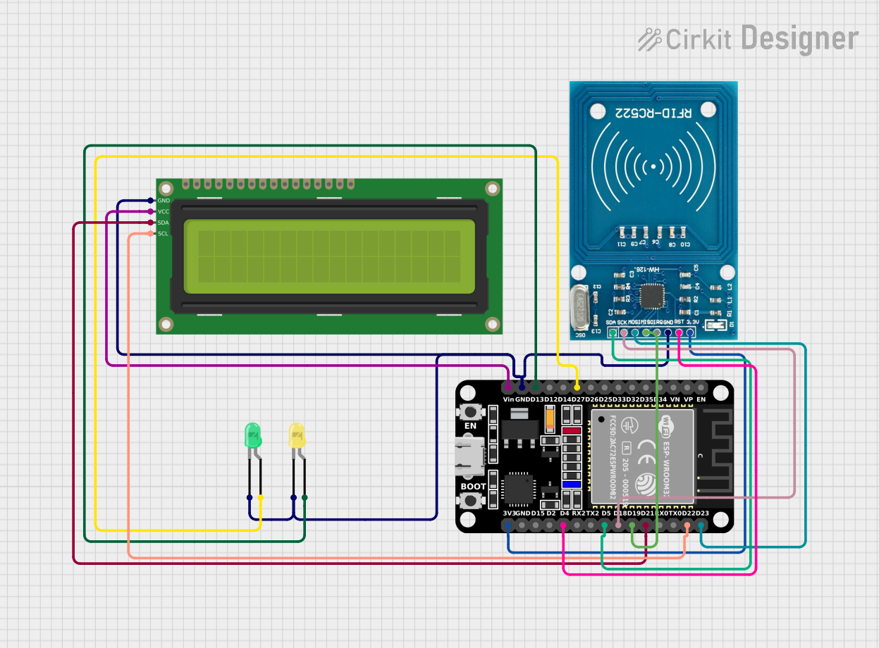
This circuit integrates an ESP32 microcontroller with an RFID-RC522 module, two LEDs (one yellow and one green), and a 16x2 I2C LCD display. The ESP32 serves as the central processing unit, controlling the RFID reader for tag scanning and providing output indications through the LEDs. The LCD display is used to show information or status messages. The RFID-RC522 module is powered by a 3.3V supply from the ESP32 and communicates with it using SPI protocol. The LEDs are directly driven by the GPIO pins of the ESP32, and the LCD communicates over the I2C bus.
Component List
ESP32 (30 pin)
- Description: A microcontroller with Wi-Fi and Bluetooth capabilities, featuring a wide range of GPIO pins for interfacing with various peripherals.
- Pins: EN, VP, VN, D34, D35, D32, D33, D25, D26, D27, D14, D12, D13, GND, Vin, D23, D22, TX0, RX0, D21, D19, D18, D5, TX2, RX2, D4, D2, D15, 3V3
RFID-RC522
- Description: An RFID reader module that operates at 13.56 MHz, capable of reading and writing to RFID tags.
- Pins: VCC (3.3V), RST, GND, IRQ, MISO, MOSI, SCK, SDA
LED: Two Pin (yellow)
- Description: A yellow LED for indication purposes.
- Pins: cathode, anode
LED: Two Pin (green)
- Description: A green LED for indication purposes.
- Pins: cathode, anode
16x2 I2C LCD
- Description: A 16-character by 2-line LCD display with an I2C interface for displaying text.
- Pins: GND, VCC, SDA, SCL
Wiring Details
ESP32 (30 pin)
- D27 connected to the anode of the green LED
- D13 connected to the anode of the yellow LED
- GND connected to the cathodes of both LEDs, GND of RFID-RC522, and GND of 16x2 I2C LCD
- Vin connected to VCC of the 16x2 I2C LCD
- D23 (MOSI) connected to MOSI of RFID-RC522
- D22 (SCL) connected to SCL of 16x2 I2C LCD
- D21 (SDA) connected to SDA of 16x2 I2C LCD
- D19 (MISO) connected to MISO of RFID-RC522
- D18 (SCK) connected to SCK of RFID-RC522
- D5 (SDA) connected to SDA of RFID-RC522
- D4 (RST) connected to RST of RFID-RC522
- 3V3 connected to VCC (3.3V) of RFID-RC522
RFID-RC522
- VCC (3.3V) connected to 3V3 of ESP32
- RST connected to D4 of ESP32
- GND connected to GND of ESP32, both LEDs, and 16x2 I2C LCD
- IRQ not connected
- MISO connected to D19 of ESP32
- MOSI connected to D23 of ESP32
- SCK connected to D18 of ESP32
- SDA connected to D5 of ESP32
LED: Two Pin (yellow)
- anode connected to D13 of ESP32
- cathode connected to GND of ESP32
LED: Two Pin (green)
- anode connected to D27 of ESP32
- cathode connected to GND of ESP32
16x2 I2C LCD
- GND connected to GND of ESP32
- VCC connected to Vin of ESP32
- SDA connected to D21 of ESP32
- SCL connected to D22 of ESP32
Documented Code
Since no code was provided for the microcontrollers in the circuit, this section is left blank. In a typical scenario, this section would include the source code for the ESP32, detailing the initialization and control of the peripherals such as the RFID-RC522, LEDs, and the LCD display, along with comments explaining the functionality of each part of the code.