
Circuit Documentation
Summary of the Circuit
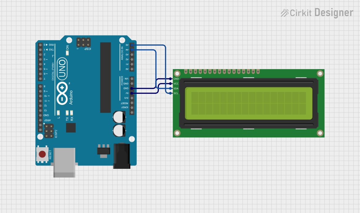
This circuit consists of an Arduino UNO microcontroller board interfaced with a 16x2 I2C LCD display. The Arduino UNO provides the necessary power and data connections to the LCD display through the I2C communication protocol. The purpose of this circuit is to enable the display of information on the LCD using the Arduino UNO as the controlling unit.
Component List
Arduino UNO
- Description: A microcontroller board based on the ATmega328P.
- Pins: UNUSED, IOREF, Reset, 3.3V, 5V, GND, Vin, A0-A5, SCL, SDA, AREF, D0-D13.
- Purpose: Acts as the main controller for the circuit, providing I/O capabilities and power to the LCD display.
16x2 I2C LCD
- Description: An alphanumeric liquid crystal display with 16 characters per line and 2 lines, equipped with an I2C interface.
- Pins: GND, VCC, SDA, SCL.
- Purpose: To display text or data output from the Arduino UNO.
Wiring Details
Arduino UNO
- 5V: Provides power to the 16x2 I2C LCD display.
- GND: Common ground with the 16x2 I2C LCD display.
- A4 (SDA): I2C data line connected to the SDA pin of the 16x2 I2C LCD.
- A5 (SCL): I2C clock line connected to the SCL pin of the 16x2 I2C LCD.
16x2 I2C LCD
- VCC: Connected to the 5V output from the Arduino UNO.
- GND: Connected to the ground (GND) on the Arduino UNO.
- SDA: I2C data line connected to the A4 (SDA) pin on the Arduino UNO.
- SCL: I2C clock line connected to the A5 (SCL) pin on the Arduino UNO.
Documented Code
Arduino UNO Code (sketch.ino)
void setup() {
  // put your setup code here, to run once:

}

void loop() {
  // put your main code here, to run repeatedly:

}
Note: The provided code is a template and does not include specific instructions for interacting with the 16x2 I2C LCD. To complete the circuit functionality, the code needs to be written to initialize the I2C communication and to send data to the LCD for display.