
ESP-32 and Arduino Uno R3 Based RS485 Communication System with Ultrasonic Sensing and Motor Control
View and Edit Project In Cirkit Designer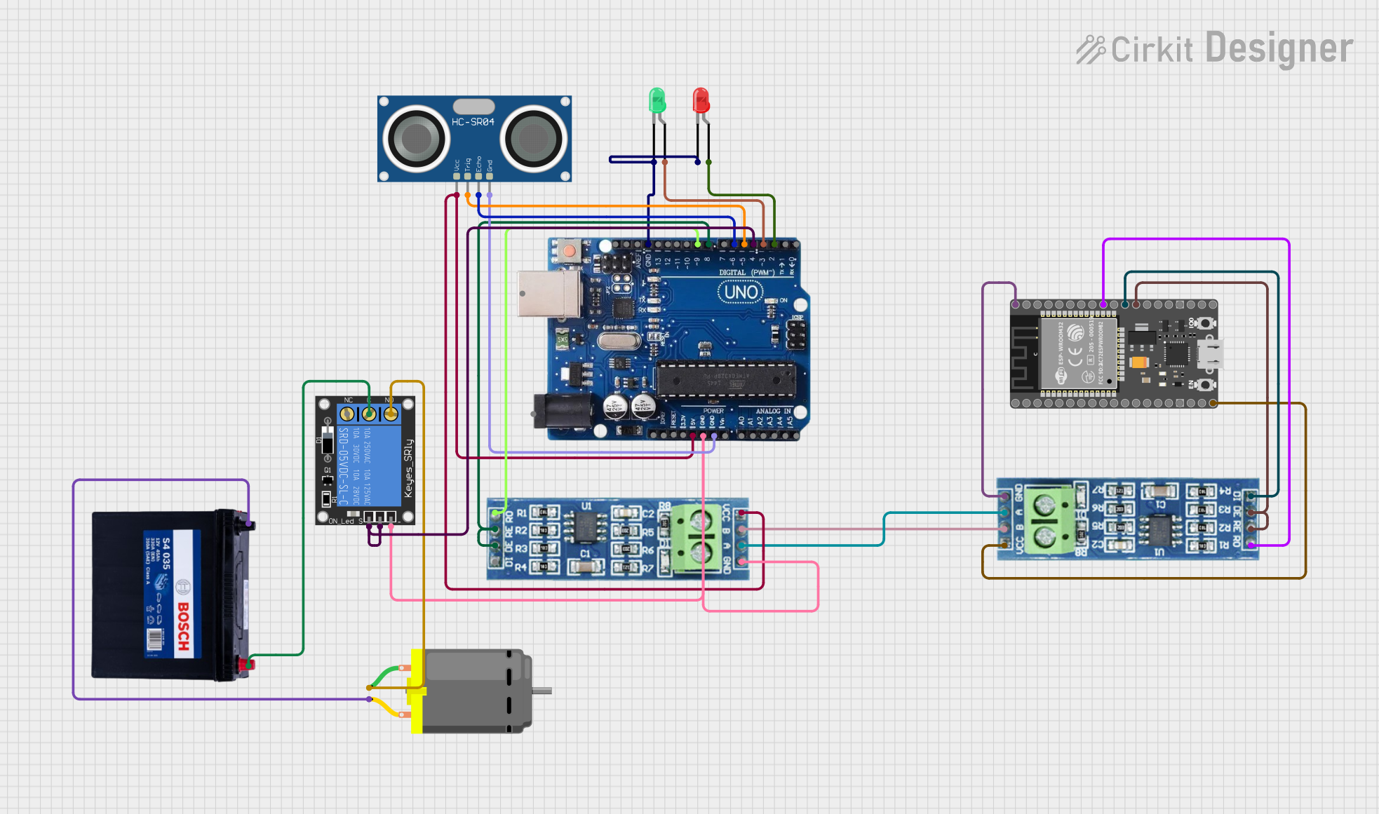
Circuit Documentation
Summary of the Circuit
This circuit is designed to interface an ESP-32 microcontroller with an RS485 transceiver for serial communication. It also includes an Arduino Uno R3 microcontroller for additional control and interfacing with an HC-SR04 ultrasonic sensor, LEDs, a relay, and a DC motor. The circuit is powered by a 12V 200Ah battery, which also powers the relay and the DC motor. The ESP-32 and Arduino Uno are responsible for controlling the various components and handling the logic of the system.
Component List
RS485 Transceiver
- Description: A transceiver module for RS485 serial communication.
- Pins: VCC, RO, RE, GND, B, A, DE, DI
LED: Two Pin (green)
- Description: A green LED indicator.
- Pins: cathode, anode
LED: Two Pin (red)
- Description: A red LED indicator.
- Pins: cathode, anode
HC-SR04 Ultrasonic Sensor
- Description: An ultrasonic distance sensor.
- Pins: VCC, TRIG, ECHO, GND
HiLetGo ESP-32
- Description: A microcontroller with Wi-Fi and Bluetooth capabilities.
- Pins: 3.3V, EN, GPIOs, GND, VIN
Arduino Uno R3
- Description: A microcontroller board based on the ATmega328P.
- Pins: USB Port, Power Jack, IOREF, RESET, 3.3V, 5V, GND, VIN, Analog Inputs, Digital I/O
1-Channel Relay (5V 10A)
- Description: A relay module for controlling high power devices.
- Pins: NC, signal, C, power, NO, ground
DC Motor
- Description: A motor that converts electrical energy into mechanical energy.
- Pins: pin 1, pin 2
12V 200Ah Battery
- Description: A high-capacity battery for providing power to the circuit.
- Pins: GND, 12V
Wiring Details
RS485 Transceiver
- VCC: Connected to the power supply (ESP-32 VIN or Arduino Uno 5V).
- RO: Connected to ESP-32 GPIO18 or Arduino Uno pin 9.
- RE and DE: Connected together and to ESP-32 GPIO16 or Arduino Uno pin 8.
- GND: Connected to the common ground.
- B and A: Interconnected between two RS485 transceivers for differential communication.
LED: Two Pin (green)
- cathode: Connected to the common ground.
- anode: Connected to Arduino Uno pin 3.
LED: Two Pin (red)
- cathode: Connected to the common ground.
- anode: Connected to Arduino Uno pin 2.
HC-SR04 Ultrasonic Sensor
- VCC: Connected to the power supply (RS485 VCC or Arduino Uno 5V).
- TRIG: Connected to Arduino Uno pin 5.
- ECHO: Connected to Arduino Uno pin 6.
- GND: Connected to the common ground.
HiLetGo ESP-32
- VIN: Connected to the power supply (RS485 VCC).
- GPIO18: Connected to RS485 RO.
- GPIO16: Connected to RS485 RE and DE.
- GND: Connected to the common ground.
- GPIO17: Connected to RS485 DI.
Arduino Uno R3
- 5V: Connected to the power supply (RS485 VCC).
- GND: Connected to the common ground.
- Digital pins 2, 3, 4, 5, 6, 8, 9: Connected to LEDs, relay, and HC-SR04 sensor as specified in the wiring details.
1-Channel Relay (5V 10A)
- ground: Connected to the common ground.
- signal: Connected to Arduino Uno pin 4.
- power: Connected to the power supply (Arduino Uno 5V).
- C: Connected to the 12V battery positive terminal.
- NO: Connected to DC Motor pin 1.
DC Motor
- pin 1: Connected to the relay NO terminal.
- pin 2: Connected to the 12V battery negative terminal.
12V 200Ah Battery
- GND: Connected to the common ground and DC Motor pin 2.
- 12V: Connected to the relay C terminal.
Documented Code
There is no code provided for the microcontrollers in this circuit. The code would typically include initialization of GPIO pins, setup of serial communication protocols, control logic for the relay, and reading from the ultrasonic sensor. Without the code, we cannot document the specific functions and routines that would be implemented on the ESP-32 and Arduino Uno microcontrollers.