
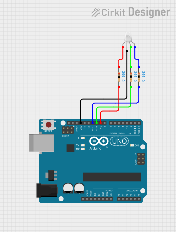
Circuit Documentation
Summary
This document describes a simple circuit that controls an RGB LED using an Arduino UNO microcontroller. The RGB LED will cycle through red, green, and blue colors, with each color being illuminated for one second before switching to the next color. The circuit includes current-limiting resistors for each LED color channel to prevent damage to the LED.
Component List
Arduino UNO
- Description: A microcontroller board based on the ATmega328P.
- Purpose: Acts as the control unit for the RGB LED, cycling through the colors.
- Pins Used: GND, D9, D10, D11.
RGB LED (Wokwi compatible)
- Description: A four-pin LED with red, green, and blue emitters.
- Purpose: Displays colors as instructed by the Arduino UNO.
- Pins Used: R, G, B, COM.
Resistors (3x)
- Description: Three resistors, each with a resistance of 200 Ohms.
- Purpose: Limit the current flowing through each channel of the RGB LED to protect it.
- Pins Used: pin1, pin2.
Wiring Details
Arduino UNO
- GND is connected to the common (COM) pin of the RGB LED.
- D9 is connected through a 200 Ohm resistor to the blue (B) channel of the RGB LED.
- D10 is connected through a 200 Ohm resistor to the green (G) channel of the RGB LED.
- D11 is connected through a 200 Ohm resistor to the red (R) channel of the RGB LED.
RGB LED (Wokwi compatible)
- COM pin is connected to the GND pin on the Arduino UNO.
- R channel is connected to the Arduino UNO's D11 pin through a 200 Ohm resistor.
- G channel is connected to the Arduino UNO's D10 pin through a 200 Ohm resistor.
- B channel is connected to the Arduino UNO's D9 pin through a 200 Ohm resistor.
Resistors
200 Ohm Resistor for Red Channel
- pin1 is connected to the R channel of the RGB LED.
- pin2 is connected to the D11 pin on the Arduino UNO.
200 Ohm Resistor for Green Channel
- pin1 is connected to the G channel of the RGB LED.
- pin2 is connected to the D10 pin on the Arduino UNO.
200 Ohm Resistor for Blue Channel
- pin1 is connected to the B channel of the RGB LED.
- pin2 is connected to the D9 pin on the Arduino UNO.
Documented Code
/*
 * This Arduino sketch controls an RGB LED connected to an Arduino UNO.
 * The LED will blink each color (Red, Green, Blue) sequentially with
 * a delay of 1 second between each color.
 */

// Pin definitions
const int redPin = 9;
const int greenPin = 10;
const int bluePin = 11;

void setup() {
  // Initialize the digital pins as outputs
  pinMode(redPin, OUTPUT);
  pinMode(greenPin, OUTPUT);
  pinMode(bluePin, OUTPUT);
}

void loop() {
  // Turn on the red LED
  digitalWrite(redPin, HIGH);
  delay(1000); // Wait for 1 second
  digitalWrite(redPin, LOW);

  // Turn on the green LED
  digitalWrite(greenPin, HIGH);
  delay(1000); // Wait for 1 second
  digitalWrite(greenPin, LOW);

  // Turn on the blue LED
  digitalWrite(bluePin, HIGH);
  delay(1000); // Wait for 1 second
  digitalWrite(bluePin, LOW);
}
Filename: sketch.ino
Description: The code defines three pins connected to the RGB LED through resistors. It sets these pins as outputs in the setup() function. In the loop() function, it sequentially turns on each color for one second, then turns it off before moving to the next color. This cycle repeats indefinitely.