ESP8266 NodeMCU Controlled Dual LED Circuit
Circuit Documentation
Summary of the Circuit
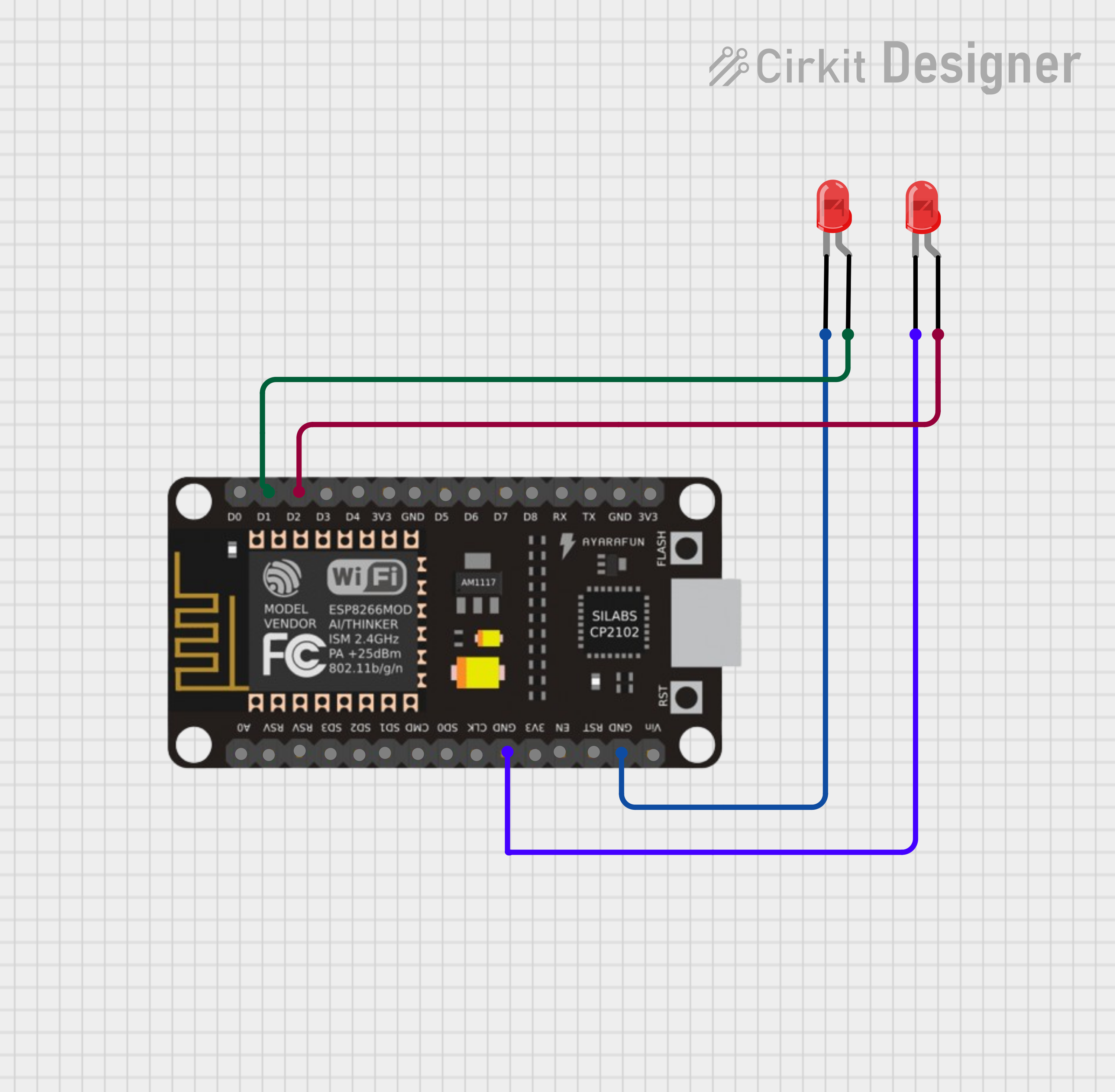
This circuit consists of an ESP8266 NodeMCU microcontroller unit (MCU) and two red LEDs. The ESP8266 NodeMCU is a Wi-Fi capable microcontroller with a variety of digital pins that can be used for interfacing with various electronic components. In this circuit, two of its digital pins are used to control the LEDs. The LEDs are connected to the digital pins through their anodes, and their cathodes are connected to the ground (GND) pin of the ESP8266 NodeMCU, completing the circuit for each LED.
Component List
ESP8266 NodeMCU
- Description: A Wi-Fi capable microcontroller with multiple digital I/O pins.
- Pins: D0, D1, D2, D3, D4, 3V3, GND, D5, D6, D7, D8, RX, TX, A0, RSV, SD3, SD2, SD1, CMD, SD0, CLK, EN, RST, VIN
LED: Two Pin (red)
- Description: A standard red LED with two pins: anode and cathode.
- Pins: cathode, anode
Wiring Details
ESP8266 NodeMCU
- D1: Connected to the anode of the first red LED.
- D2: Connected to the anode of the second red LED.
- GND: Connected to the cathodes of both red LEDs.
LED: Two Pin (red) #1
- Anode: Connected to the D1 pin of the ESP8266 NodeMCU.
- Cathode: Connected to the GND pin of the ESP8266 NodeMCU.
LED: Two Pin (red) #2
- Anode: Connected to the D2 pin of the ESP8266 NodeMCU.
- Cathode: Connected to the GND pin of the ESP8266 NodeMCU.
Documented Code
No code has been provided for the microcontroller. To control the LEDs, code should be written and uploaded to the ESP8266 NodeMCU to define the behavior of the digital pins D1 and D2 (e.g., to turn the LEDs on or off, or to make them blink). Since no code is available, this section cannot be documented further. However, a simple example to blink an LED connected to D1 might look like this in the Arduino IDE:
void setup() {
  pinMode(D1, OUTPUT); // Initialize D1 as an output
}

void loop() {
  digitalWrite(D1, HIGH); // Turn the LED on
  delay(1000);           // Wait for a second
  digitalWrite(D1, LOW);  // Turn the LED off
  delay(1000);           // Wait for a second
}
This example code would need to be duplicated for D2 if both LEDs are to blink independently.