Cirkit Designer
Your all-in-one circuit design IDE
Home /
Project Documentation
Arduino UNO Controlled Dual Servo Joystick Interface
Circuit Documentation
Summary of the Circuit
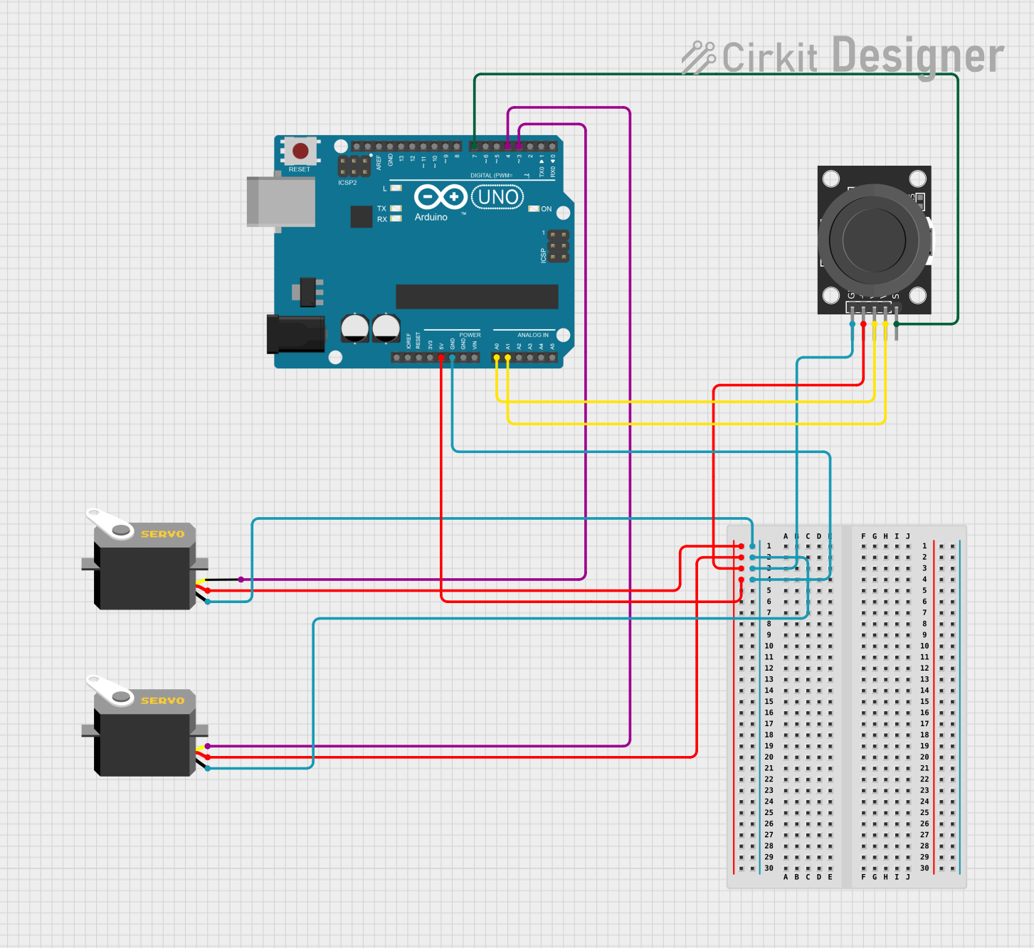
This circuit is designed to interface an Arduino UNO with two servo motors and a KY-023 Dual Axis Joystick Module. The Arduino UNO acts as the central controller, reading inputs from the joystick and controlling the position of the servo motors accordingly. The joystick provides two axes of control and a pushbutton switch, which can be used for various interactive applications. The servo motors are powered by the Arduino and receive pulse width modulation (PWM) signals to set their positions.
Component List
Arduino UNO
- Description: A microcontroller board based on the ATmega328P.
- Purpose: Acts as the central processing unit of the circuit, reading joystick inputs and controlling servo positions.
Servo (x2)
- Description: A rotary actuator or linear actuator that allows for precise control of angular or linear position.
- Purpose: Responds to PWM signals from the Arduino to move to desired positions.
KY-023 Dual Axis Joystick Module
- Description: A joystick module with two potentiometers (one for each axis) and a pushbutton switch.
- Purpose: Provides user input to the Arduino for controlling the servos.
Wiring Details
Arduino UNO
- 5V: Provides power to the servo motors and the joystick module.
- GND: Common ground for the circuit.
- A0: Reads the horizontal axis (VRx) of the joystick.
- A1: Reads the vertical axis (VRy) of the joystick.
- D7: Reads the state of the joystick pushbutton switch (SW).
- D3: Outputs PWM signal to control one servo motor (pulse).
- D4: Outputs PWM signal to control the other servo motor (pulse).
Servo 1
- vcc: Connected to the 5V output from the Arduino.
- gnd: Connected to the ground (GND) on the Arduino.
- pulse: Receives PWM signal from pin D3 on the Arduino.
Servo 2
- vcc: Connected to the 5V output from the Arduino.
- gnd: Connected to the ground (GND) on the Arduino.
- pulse: Receives PWM signal from pin D4 on the Arduino.
KY-023 Dual Axis Joystick Module
- +5V: Connected to the 5V output from the Arduino.
- GND: Connected to the ground (GND) on the Arduino.
- VRx: Connected to analog input A0 on the Arduino.
- VRy: Connected to analog input A1 on the Arduino.
- SW: Connected to digital pin D7 on the Arduino.
Documented Code
void setup() {
  // put your setup code here, to run once:

}

void loop() {
  // put your main code here, to run repeatedly:

}
Filename: sketch.ino
Note: The provided code is a template and does not contain any functional code to operate the circuit. It needs to be completed with the logic for reading the joystick inputs and controlling the servo motors.