
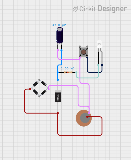
Circuit Documentation
Summary of the Circuit
This circuit appears to be a simple signal processing circuit that utilizes a piezo sensor to detect vibrations or pressure changes. The signal from the piezo sensor is then rectified by a diode and a bridge rectifier, possibly to ensure a unidirectional current flow for further processing. An electrolytic capacitor is used, likely for smoothing the rectified signal. A pushbutton is included, which may serve as a manual control element in the circuit. Additionally, there is a resistor-LED pair, which could be used as an indicator light. The absence of microcontroller code suggests that this circuit operates without programmable control logic.
Component List
Piezo Sensor
- Pins:
+,- - Description: A sensor that generates a voltage when pressure is applied.
1N4007 Rectifier Diode
- Pins:
Cathode,Anode - Description: A diode that allows current to flow in only one direction, typically used for rectification.
Bridge Rectifier
- Pins:
Source_in-,source_out-,source_out+,source_in+ - Description: A component that converts alternating current (AC) to direct current (DC).
Pushbutton
- Pins:
Pin 3 (out),Pin 4 (out),Pin 1 (in),Pin 2 (in) - Description: A manually operated switch that can open or close a circuit.
Resistor
- Pins:
pin1,pin2 - Description: A passive two-terminal electrical component that implements electrical resistance.
- Properties: Resistance - 1000 Ohms
LED: Two Pin (white)
- Pins:
cathode,anode - Description: A light-emitting diode that emits white light when current flows through it.
Electrolytic Capacitor
- Pins:
-,+ - Description: A capacitor with a larger capacitance per unit volume than other types, used for filtering or energy storage.
- Properties: Capacitance - 0.00004702304129023221 Farads
Wiring Details
Piezo Sensor
+connected to Anode of 1N4007 Rectifier Diode and source_out- of Bridge Rectifier-connected to - of Electrolytic Capacitor, Pin 2 (in) of Pushbutton, and source_out+ of Bridge Rectifier
1N4007 Rectifier Diode
Anodeconnected to + of Piezo SensorCathodeconnected to + of Electrolytic Capacitor and pin1 of Resistor
Bridge Rectifier
Source_in-(not connected in provided net list)source_out-connected to + of Piezo Sensorsource_out+connected to - of Piezo Sensorsource_in+(not connected in provided net list)
Pushbutton
Pin 3 (out)(not connected in provided net list)Pin 4 (out)connected to anode of LED: Two Pin (white)Pin 1 (in)(not connected in provided net list)Pin 2 (in)connected to - of Piezo Sensor
Resistor
pin1connected to Cathode of 1N4007 Rectifier Diodepin2connected to cathode of LED: Two Pin (white)
LED: Two Pin (white)
anodeconnected to Pin 4 (out) of Pushbuttoncathodeconnected to pin2 of Resistor
Electrolytic Capacitor
+connected to Cathode of 1N4007 Rectifier Diode-connected to - of Piezo Sensor
Documented Code
No code has been provided for any microcontrollers in the circuit. Therefore, there is no code documentation to include in this section. If code becomes available at a later date, it should be documented here following the same structure and level of detail as the rest of this document.