Arduino Nano Controlled NRF24L01 Wireless Joystick
Circuit Documentation
Summary
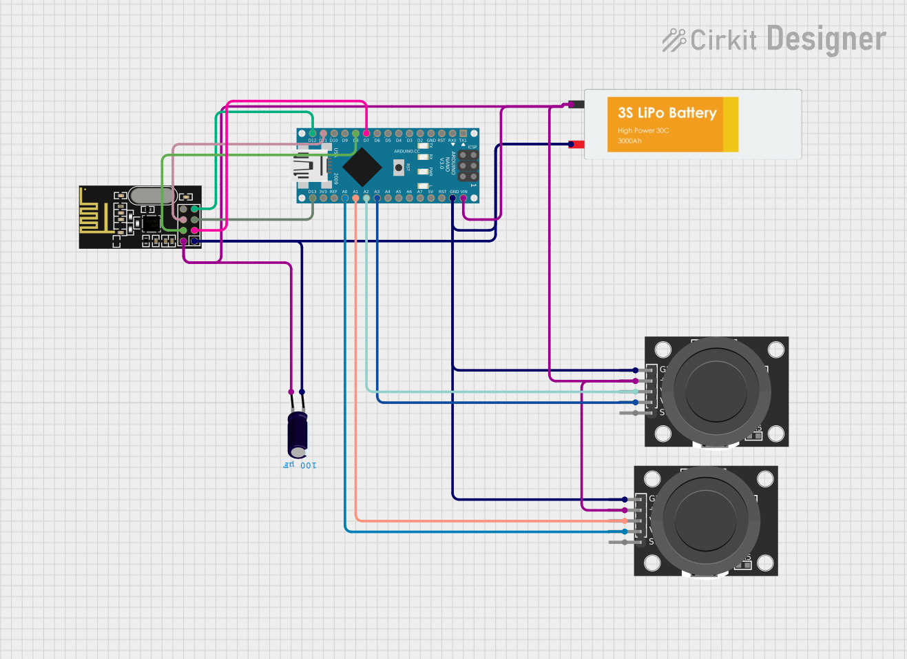
This circuit is designed to control a 4-channel transmitter using an Arduino Nano as the central processing unit. It interfaces with an NRF24L01 module for wireless communication and two KY-023 Dual Axis Joystick Modules for user input. A Lipo Battery provides power to the system, and an Electrolytic Capacitor is used for voltage smoothing. The Arduino Nano reads the joystick positions and transmits the data wirelessly via the NRF24L01 module.
Component List
Arduino Nano
- Microcontroller board based on the ATmega328P
- It has a variety of digital and analog I/O pins
- Used for reading joystick inputs and controlling the NRF24L01 module
Electrolytic Capacitor
- Capacitance: 0.0001 Farads
- Used for voltage smoothing in the power supply circuit
NRF24L01
- 2.4GHz wireless transceiver module
- Interfaces with the Arduino Nano for wireless communication
KY-023 Dual Axis Joystick Module (x2)
- Provides two analog outputs corresponding to the X and Y positions of the joystick
- Includes a pushbutton switch
- Used for user input to control the transmitter
Lipo Battery
- Provides power to the circuit
Wiring Details
Arduino Nano
D7connected to NRF24L01 CED8connected to NRF24L01 CSND11/MOSIconnected to NRF24L01 MOSID12/MISOconnected to NRF24L01 MISOD13/SCKconnected to NRF24L01 SCKA0connected to KY-023 Joystick Module VRyA1connected to KY-023 Joystick Module VRxA2connected to KY-023 Joystick Module VRxA3connected to KY-023 Joystick Module VRyVINconnected to the positive side of the power supply netGNDconnected to the ground net
Electrolytic Capacitor
+connected to the positive side of the power supply net-connected to the ground net
NRF24L01
CEconnected to Arduino Nano D7CSNconnected to Arduino Nano D8MOSIconnected to Arduino Nano D11/MOSIMISOconnected to Arduino Nano D12/MISOSCKconnected to Arduino Nano D13/SCKVCC (3V)connected to the positive side of the power supply netGNDconnected to the ground net
KY-023 Dual Axis Joystick Module
GNDconnected to the ground net+5Vconnected to the positive side of the power supply netVRxconnected to Arduino Nano A1 and A2VRyconnected to Arduino Nano A0 and A3
Lipo Battery
VCCconnected to the ground netGNDconnected to the positive side of the power supply net
Documented Code
// 4 Channel Transmitter | 4 Kanal Verici

#include <SPI.h>
#include <nRF24L01.h>
#include <RF24.h>

const uint64_t pipeOut = 0xE9E8F0F0E1LL;   //IMPORTANT: The same as in the receiver 0xE9E8F0F0E1LL | Bu adres alıcı ile aynı olmalı
RF24 radio(7, 8); // select CE,CSN pin | CE ve CSN pinlerin seçimi

struct Signal {
  byte throttle;
  byte pitch;
  byte roll;
  byte yaw;
};

Signal data;

void ResetData()
{
  data.throttle = 127; // Motor Stop (254/2=127)| Motor Kapalı (Signal lost position | sinyal kesildiğindeki pozisyon)
  data.pitch = 127; // Center | Merkez (Signal lost position | sinyal kesildiğindeki pozisyon)
  data.roll = 127; // Center | merkez (Signal lost position | sinyal kesildiğindeki pozisyon)
  data.yaw = 127; // Center | merkez (Signal lost position | sinyal kesildiğindeki pozisyon)
}

void setup()
{
  //Start everything up

  radio.begin();
  radio.openWritingPipe(pipeOut);
  radio.stopListening(); //start the radio comunication for Transmitter | Verici olarak sinyal iletişimi başlatılıyor
  ResetData();
}

// Joystick center and its borders | Joystick merkez ve sınırları

int mapJoystickValues(int val, int lower, int middle, int upper, bool reverse)
{
  val = constrain(val, lower, upper);
  if ( val < middle )
    val = map(val, lower, middle, 0, 128);
  else
    val = map(val, middle, upper, 128, 255);
  return ( reverse ? 255 - val : val );
}

void loop()
{
  // Control Stick Calibration | Kumanda Kol Kalibrasyonları
  // Setting may be required for the correct values of the control levers. | Kolların doğru değerleri için ayar gerekebilir.

  data.throttle = mapJoystickValues( analogRead(A0), 524, 524, 1015, true );
  data.roll = mapJoystickValues( analogRead(A1), 12, 524, 1020, true );      // "true" or "false" for servo direction | "true" veya "false" servo yönünü belirler
  data.pitch = mapJoystickValues( analogRead(A2), 12, 524, 1020, true );     // "true" or "false" for servo direction | "true" veya "false" servo yönünü belirler
  data.yaw = mapJoystickValues( analogRead(A3), 12, 524, 1020, true );       // "true" or "false" for servo direction | "true" veya "false" servo yönünü belirler

  radio.write(&data, sizeof(Signal));
}
This code is responsible for reading the joystick values, mapping them to a range suitable for the application, and transmitting the data wirelessly using the NRF24L01 module. The mapJoystickValues function is used to convert the raw analog readings from the joystick into a format that can be used for controlling servos or motors. The ResetData function initializes the control signals to a neutral position in case of signal loss. The setup function initializes the radio module, and the loop function continuously reads the joystick inputs and sends the data.