Cirkit Designer
Your all-in-one circuit design IDE
Home /
Project Documentation
Arduino UNO and VC-02 Module-Based Voice-Controlled Stepper Motor System
Circuit Documentation
Summary
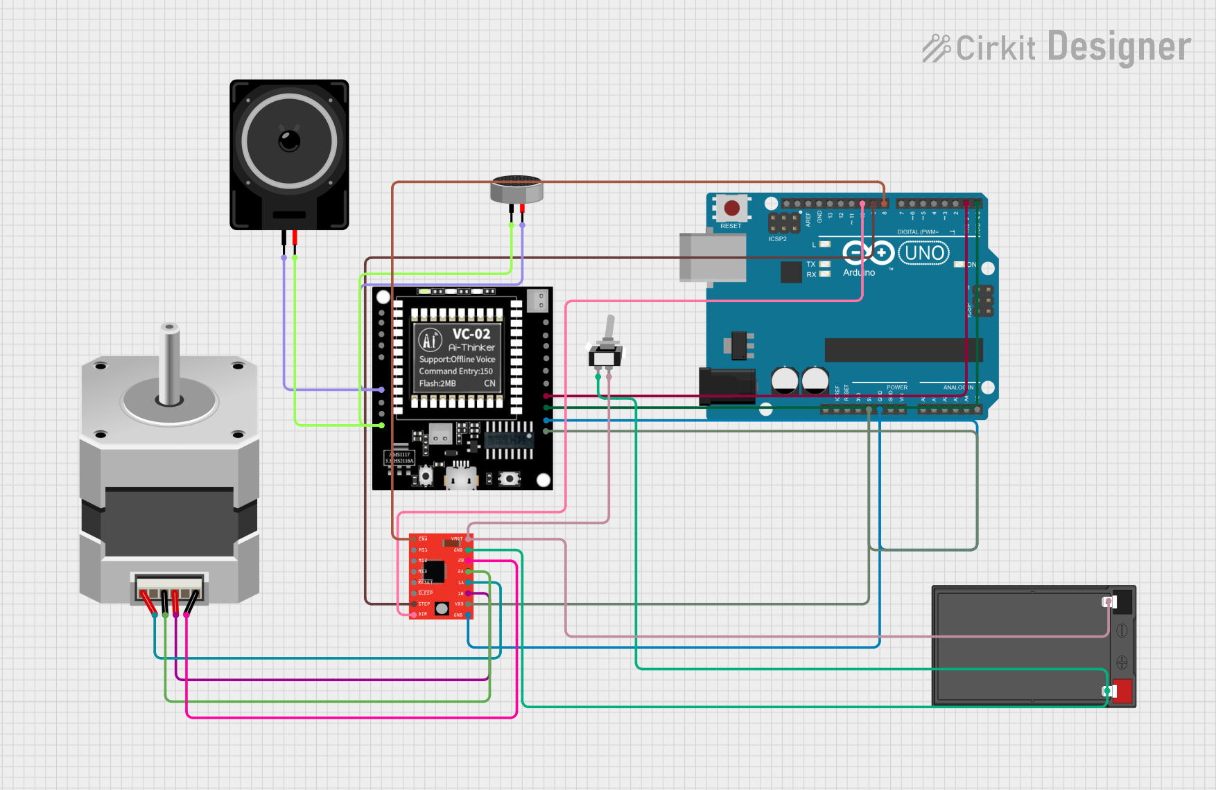
This circuit integrates various components including a VC-02 Module, a Stepper Motor, a Condenser Microphone, an Arduino UNO, an A4988 Stepper Motor Driver, a 12V 7Ah Battery, a Toggle Switch, and a Loudspeaker. The circuit is designed to control a stepper motor and communicate with a VC-02 module while also handling audio input and output through a condenser microphone and a loudspeaker.
Component List
VC-02 Module
- Description: A versatile module for audio processing and communication.
- Pins: NC, TCK OR IOB0, TMS OR IOB1, GND, Vcc, DAC_L, DAS_R, 3.3V O, SDA_5V, SCL_5V, SDA OR IOB3, SCL OR IOB2, IOA27, IOB8, RX(IOB6), TX(IOB7)
Stepper Motor (Bipolar)
- Description: A bipolar stepper motor for precise control of rotational position.
- Pins: D, B, C, A
Condenser Microphone
- Description: A microphone for capturing audio signals.
- Pins: pin1, pin2
Arduino UNO
- Description: A microcontroller board based on the ATmega328P.
- Pins: UNUSED, IOREF, Reset, 3.3V, 5V, GND, Vin, A0, A1, A2, A3, A4, A5, SCL, SDA, AREF, D13, D12, D11, D10, D9, D8, D7, D6, D5, D4, D3, D2, D1, D0
A4988 Stepper Motor Driver (Red)
- Description: A driver module for controlling bipolar stepper motors.
- Pins: ENABLE, MS1, MS2, MS3, RESET, SLEEP, STEP, DIR, VMOT, GND, 2B, 2A, 1A, 1B, VDD
12V 7Ah Battery
- Description: A rechargeable battery providing 12V power.
- Pins: 12v +, 12v -
Toggle Switch SPST
- Description: A single-pole single-throw switch for controlling power.
- Pins: L1, COM
Loudspeaker
- Description: A speaker for audio output.
- Pins: pin1, pin2
Wiring Details
VC-02 Module
- DAC_L connected to Condenser Microphone pin2 and Loudspeaker pin1
- GND connected to Condenser Microphone pin1, Loudspeaker pin2, Arduino UNO GND, and A4988 Stepper Motor Driver GND
- RX(IOB6) connected to Arduino UNO D1
- TX(IOB7) connected to Arduino UNO D0
- Vcc connected to Arduino UNO 5V and A4988 Stepper Motor Driver VDD
Stepper Motor (Bipolar)
- D connected to A4988 Stepper Motor Driver 2B
- B connected to A4988 Stepper Motor Driver 1B
- C connected to A4988 Stepper Motor Driver 2A
- A connected to A4988 Stepper Motor Driver 1A
Condenser Microphone
- pin1 connected to VC-02 Module GND and Loudspeaker pin2
- pin2 connected to VC-02 Module DAC_L and Loudspeaker pin1
Arduino UNO
- D1 connected to VC-02 Module RX(IOB6)
- D0 connected to VC-02 Module TX(IOB7)
- GND connected to VC-02 Module GND and A4988 Stepper Motor Driver GND
- 5V connected to VC-02 Module Vcc and A4988 Stepper Motor Driver VDD
- D10 connected to A4988 Stepper Motor Driver DIR
- D9 connected to A4988 Stepper Motor Driver STEP
- D8 connected to A4988 Stepper Motor Driver ENABLE
A4988 Stepper Motor Driver (Red)
- GND connected to Arduino UNO GND and VC-02 Module GND
- VDD connected to Arduino UNO 5V and VC-02 Module Vcc
- DIR connected to Arduino UNO D10
- STEP connected to Arduino UNO D9
- ENABLE connected to Arduino UNO D8
- 2B connected to Stepper Motor (Bipolar) D
- 1B connected to Stepper Motor (Bipolar) B
- 2A connected to Stepper Motor (Bipolar) C
- 1A connected to Stepper Motor (Bipolar) A
- VMOT connected to Toggle Switch COM and 12V 7Ah Battery 12v -
- GND connected to Toggle Switch L1 and 12V 7Ah Battery 12v +
12V 7Ah Battery
- 12v + connected to A4988 Stepper Motor Driver GND and Toggle Switch L1
- 12v - connected to A4988 Stepper Motor Driver VMOT and Toggle Switch COM
Toggle Switch SPST
- L1 connected to 12V 7Ah Battery 12v + and A4988 Stepper Motor Driver GND
- COM connected to 12V 7Ah Battery 12v - and A4988 Stepper Motor Driver VMOT
Loudspeaker
- pin1 connected to VC-02 Module DAC_L and Condenser Microphone pin2
- pin2 connected to VC-02 Module GND and Condenser Microphone pin1
Code Documentation
Arduino UNO Code
// Pin definitions
const int stepPin = 9; // STEP pin on A4988
const int dirPin = 10; // DIR pin on A4988
const int enablePin = 8; // ENABLE pin on A4988 (if used)
const int txPin = 0; // TX pin on Arduino (connected to RX on VC-02)
const int rxPin = 1; // RX pin on Arduino (connected to TX on VC-02)

void setup() {
  // Initialize serial communication for VC-02 module
  Serial.begin(9600);

  // Initialize stepper motor control pins
  pinMode(stepPin, OUTPUT);
  pinMode(dirPin, OUTPUT);
  pinMode(enablePin, OUTPUT);

  // Enable the stepper motor driver
  digitalWrite(enablePin, LOW); // Assuming LOW enables the driver
}

void loop() {
  // Example: Rotate stepper motor
  digitalWrite(dirPin, HIGH); // Set direction
  for (int i = 0; i < 200; i++) { // Rotate 1 revolution (assuming 200 steps per revolution)
    digitalWrite(stepPin, HIGH);
    delayMicroseconds(1000); // Adjust delay for speed control
    digitalWrite(stepPin, LOW);
    delayMicroseconds(1000);
  }
  delay(1000); // Wait for a second

  // Example: Communicate with VC-02 module
  Serial.println("Hello VC-02"); // Send a message to VC-02 module
  delay(1000); // Wait for a second
}
12V 7Ah Battery Code
void setup() {
  // put your setup code here, to run once:

}

void loop() {
  // put your main code here, to run repeatedly:

}
This documentation provides a comprehensive overview of the circuit, including a summary, detailed component list, wiring details, and documented code for the microcontrollers.