Cirkit Designer
Your all-in-one circuit design IDE
Home /
Project Documentation
Arduino Mega 2560-Based Audio-Responsive LED and Stepper Motor System
Circuit Documentation
Summary
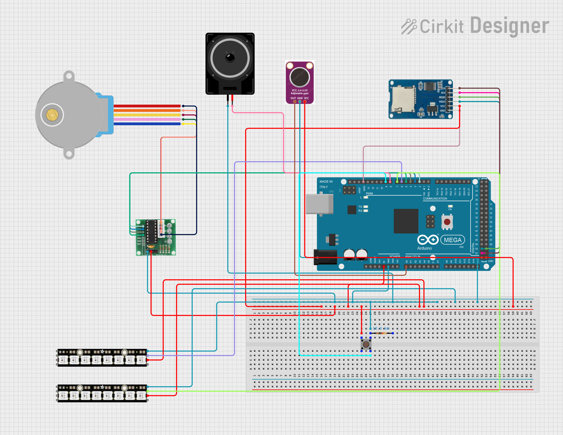
This circuit is designed to create an interactive audio-visual experience using an Arduino Mega 2560 microcontroller. The circuit includes a stepper motor, a loudspeaker, a microphone, NeoPixel LED sticks, a pushbutton, a resistor, and a micro SD card module. The system visualizes audio frequencies and beats using LEDs, controls a stepper motor to create mechanical movements, and plays audio from an SD card.
Component List
Arduino Mega 2560
- Description: Microcontroller board based on the ATmega2560.
- Pins: IOREF, RESET, 3V3, 5V, GND, VIN, A0-A15, D0-D53, AREF, SDA, SCL
28BYJ-48 Stepper Motor
- Description: 5V stepper motor used for precise control of mechanical movements.
- Pins: BLUE, PINK, YELLOW, ORANGE, RED
ULN 2003
- Description: Darlington transistor array used to drive the stepper motor.
- Pins: IN1-IN7, GND, +, COIL1-COIL5
Micro SD Card Module
- Description: Module for reading and writing to micro SD cards.
- Pins: cs, sck, mosi, miso, vcc, gnd
Loudspeaker
- Description: Audio output device.
- Pins: pin1, pin2
Adafruit NeoPixel Stick
- Description: LED stick with individually addressable RGB LEDs.
- Pins: GND, DATAOUT, +5V, DATAIN
MAX4466
- Description: Microphone amplifier module.
- Pins: OUT, GND, VCC
Pushbutton
- Description: Simple pushbutton switch.
- Pins: Pin 3 (out), Pin 4 (out), Pin 1 (in), Pin 2 (in)
Resistor
- Description: 10k Ohm resistor.
- Pins: pin1, pin2
- Properties: Resistance: 10k Ohms
Wiring Details
Arduino Mega 2560
- 5V: Connected to VCC of Micro SD Card Module, + of ULN 2003, Pin 1 (in) of Pushbutton, +5V of both Adafruit NeoPixel Sticks, VCC of MAX4466
- GND: Connected to GND of ULN 2003, Pin 3 (out) of Pushbutton, pin1 of Resistor, pin1 of Loudspeaker, GND of both Adafruit NeoPixel Sticks, GND of MAX4466, GND of Micro SD Card Module
- A0: Connected to OUT of MAX4466
- D2 PWM: Connected to IN1 of ULN 2003
- D3 PWM: Connected to IN2 of ULN 2003
- D4 PWM: Connected to IN3 of ULN 2003
- D5 PWM: Connected to IN4 of ULN 2003
- D6 PWM: Connected to DATAOUT of Adafruit NeoPixel Stick
- D7 PWM: Connected to DATAOUT of Adafruit NeoPixel Stick
- D8 PWM: Connected to pin2 of Loudspeaker
- D9 PWM: Connected to Pin 4 (out) of Pushbutton
- D52: Connected to sck of Micro SD Card Module
- D50: Connected to miso of Micro SD Card Module
- D53: Connected to cs of Micro SD Card Module
- D51: Connected to mosi of Micro SD Card Module
28BYJ-48 Stepper Motor
- BLUE: Connected to COIL1 of ULN 2003
- PINK: Connected to COIL2 of ULN 2003
- YELLOW: Connected to COIL3 of ULN 2003
- ORANGE: Connected to COIL4 of ULN 2003
- RED: Connected to COIL5 of ULN 2003
ULN 2003
- IN1: Connected to D2 PWM of Arduino Mega 2560
- IN2: Connected to D3 PWM of Arduino Mega 2560
- IN3: Connected to D4 PWM of Arduino Mega 2560
- IN4: Connected to D5 PWM of Arduino Mega 2560
- GND: Connected to GND of Arduino Mega 2560
- +: Connected to 5V of Arduino Mega 2560
- COIL1: Connected to BLUE of 28BYJ-48 Stepper Motor
- COIL2: Connected to PINK of 28BYJ-48 Stepper Motor
- COIL3: Connected to YELLOW of 28BYJ-48 Stepper Motor
- COIL4: Connected to ORANGE of 28BYJ-48 Stepper Motor
- COIL5: Connected to RED of 28BYJ-48 Stepper Motor
Micro SD Card Module
- cs: Connected to D53 of Arduino Mega 2560
- sck: Connected to D52 of Arduino Mega 2560
- mosi: Connected to D51 of Arduino Mega 2560
- miso: Connected to D50 of Arduino Mega 2560
- vcc: Connected to 5V of Arduino Mega 2560
- gnd: Connected to GND of Arduino Mega 2560
Loudspeaker
- pin1: Connected to GND of Arduino Mega 2560
- pin2: Connected to D8 PWM of Arduino Mega 2560
Adafruit NeoPixel Stick
- GND: Connected to GND of Arduino Mega 2560
- DATAOUT: Connected to D6 PWM of Arduino Mega 2560
- +5V: Connected to 5V of Arduino Mega 2560
Adafruit NeoPixel Stick
- GND: Connected to GND of Arduino Mega 2560
- DATAOUT: Connected to D7 PWM of Arduino Mega 2560
- +5V: Connected to 5V of Arduino Mega 2560
MAX4466
- OUT: Connected to A0 of Arduino Mega 2560
- GND: Connected to GND of Arduino Mega 2560
- VCC: Connected to 5V of Arduino Mega 2560
Pushbutton
- Pin 3 (out): Connected to GND of Arduino Mega 2560
- Pin 4 (out): Connected to D9 PWM of Arduino Mega 2560
- Pin 1 (in): Connected to 5V of Arduino Mega 2560
- Pin 2 (in): Not connected
Resistor
- pin1: Connected to GND of Arduino Mega 2560
- pin2: Not connected
Documented Code
//ChatGPT was used to help debugging and fix errors with the FFT Data Arrays and LEDs functions
//The LEDs for beat visulisation was inspired by this video - https://www.youtube.com/watch?v=5WP2Tjt9o2U&t=96s
//The LEDs for frequency visualisation was used the format from - https://github.com/BrainSmash/Arduino-Acoustic-Control-for-RGB-LED-Strip/blob/master/BrainSmash_AcousticControlForRGBLEDStrips_6_2019.ino
//ChatGPT was also used to merge codes together and to help create some of the comments

#include <FastLED.h>
#include <Stepper.h>
#include <TMRpcm.h>
#include <SD.h>
#include <arduinoFFT.h>

/** LED Configuration **/
#define BEAT_LED_PIN 6           // Pin for the beat LED strip
#define NOTE_LED_PIN 7           // Pin for the note LED strip
#define NUM_BEAT_LEDS 15         // Number of LEDs for beat visualization
#define NUM_NOTE_LEDS 15         // Number of LEDs for frequency visualization
#define MIC_PIN A0               // Pin for microphone input
#define SAMPLES 128              // Number of samples for FFT
#define SAMPLING_FREQ 4000       // Sampling frequency for FFT
#define PEAK_THRESHOLD 150       // Threshold for peak detection
#define PEAK_HOLD_TIME 300       // Time to hold peak visualization
#define MIC_LOW 0                // Minimum microphone value
#define MIC_HIGH 737             // Maximum microphone value
#define PLAY_BUTTON_PIN 9        // Pin for play button

// FFT Data Arrays
double vReal[SAMPLES];           // Real part of FFT input
double vImag[SAMPLES];           // Imaginary part of FFT input
ArduinoFFT<double> FFT(vReal, vImag, SAMPLES, SAMPLING_FREQ);

// LEDs
CRGB beatLeds[NUM_BEAT_LEDS