Arduino Nano Based Time Tracking System with RFID and LCD Display
Circuit Documentation
Summary of the Circuit
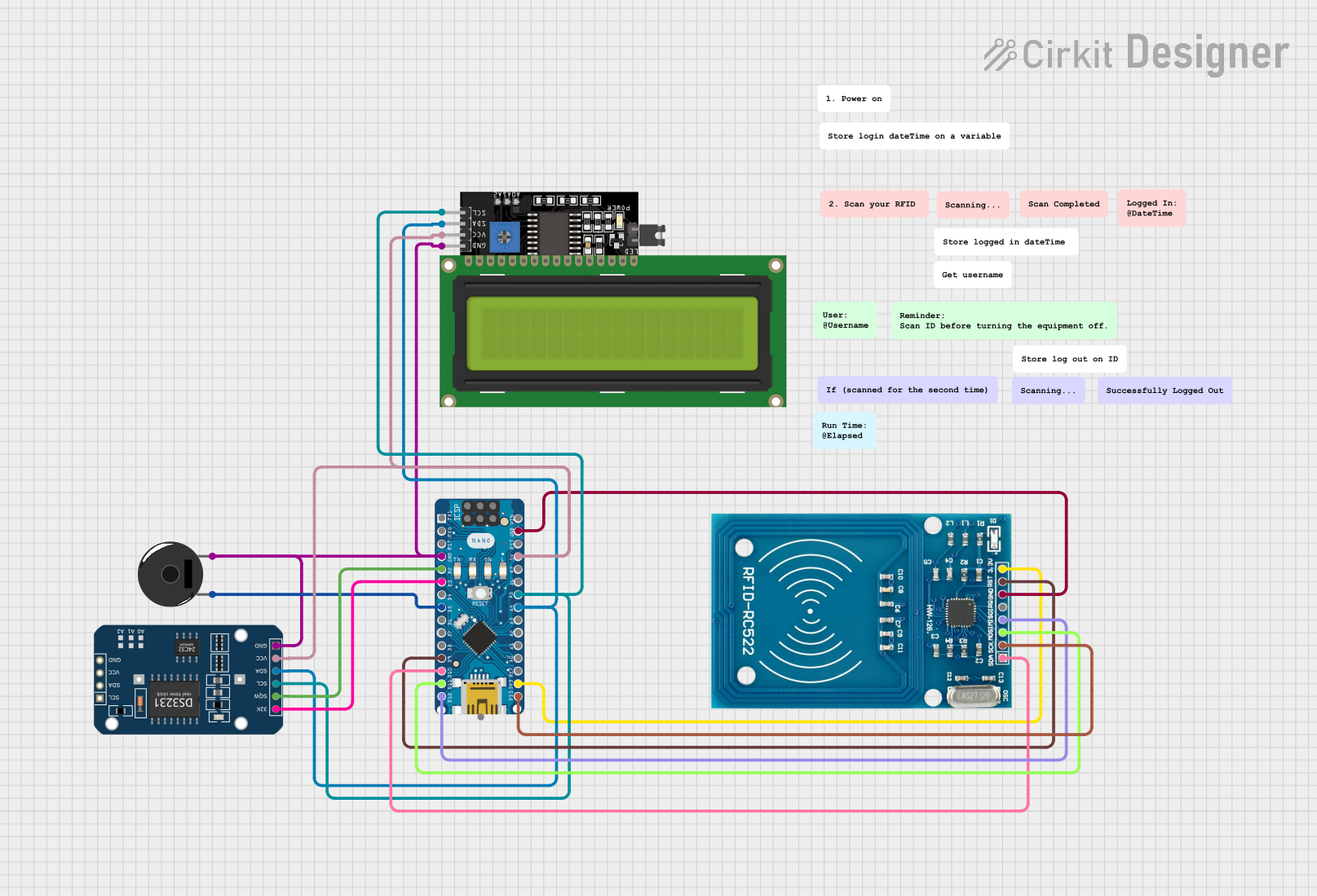
This circuit is designed to interface an Arduino Nano with a DS3231 Real-Time Clock (RTC), an LCD Display (16x4 characters) with I2C interface, a Piezo Buzzer, and an RFID-RC522 module. The Arduino Nano serves as the central processing unit, controlling the RTC for timekeeping, displaying information on the LCD, and interacting with the RFID reader for identification purposes. The Piezo Buzzer is used for audible feedback. The circuit utilizes I2C communication for the RTC and LCD, and SPI communication for the RFID module. Ground and power connections are distributed among the components to ensure proper operation.
Component List
DS3231 RTC
- Description: A precision real-time clock module with I2C interface.
- Pins: 32K, SQW, SCL, SDA, VCC, GND
LCD Display 16x4 I2C
- Description: A 16x4 character LCD display with an I2C interface for displaying data.
- Pins: SCL, SDA, VCC, GND
Piezo Buzzer
- Description: An electronic buzzer for producing sound signals.
- Pins: pin 1, pin 2
RFID-RC522
- Description: An RFID reader/writer module using SPI for communication.
- Pins: VCC (3.3V), RST, GND, IRQ, MISO, MOSI, SCK, SDA
Arduino Nano
- Description: A compact microcontroller board based on the ATmega328P, with a variety of digital and analog I/O pins.
- Pins: D1/TX, D0/RX, RESET, GND, D2, D3, D4, D5, D6, D7, D8, D9, D10, D11/MOSI, D12/MISO, VIN, 5V, A7, A6, A5, A4, A3, A2, A1, A0, AREF, 3V3, D13/SCK
Wiring Details
DS3231 RTC
- GND connected to Arduino Nano GND
- SQW connected to Arduino Nano D2
- 32K connected to Arduino Nano D3
- VCC connected to Arduino Nano 5V
- SCL connected to Arduino Nano A5 (I2C bus)
- SDA connected to Arduino Nano A4 (I2C bus)
LCD Display 16x4 I2C
- GND connected to Arduino Nano GND
- VCC connected to Arduino Nano 5V
- SCL connected to Arduino Nano A5 (I2C bus)
- SDA connected to Arduino Nano A4 (I2C bus)
Piezo Buzzer
- pin 1 connected to Arduino Nano D5
- pin 2 connected to Arduino Nano GND
RFID-RC522
- VCC (3.3V) connected to Arduino Nano 3V3
- RST connected to Arduino Nano D9
- GND connected to Arduino Nano GND
- IRQ not connected
- MISO connected to Arduino Nano D12/MISO
- MOSI connected to Arduino Nano D11/MOSI
- SCK connected to Arduino Nano D13/SCK
- SDA connected to Arduino Nano D10
Documented Code
#include <Wire.h>
#include <RTClib.h>
#include <LiquidCrystal_I2C.h>

// Initialize the LCD display with I2C address 0x27 and size 16x2
LiquidCrystal_I2C lcd(0x27, 16, 2);

// Initialize the RTC module
RTC_DS3231 rtc;

// Variables to store login and logout times
DateTime loggedIn;
DateTime loggedOut;

// Variable to store the period (AM/PM)
String period = "AM";

// Pin definitions
const byte BUZZER_PIN = 5;
const byte BUTTON_PIN = 3;

// Variables to track button state
byte lastState = LOW;  // Previous state of the button
int currentState;      // Current state of the button

void setup() {
  // Start the I2C communication
  Wire.begin();

  // Set pin modes
  pinMode(BUZZER_PIN, OUTPUT);
  pinMode(BUTTON_PIN, INPUT_PULLUP);

  // Initialize serial communication at 9600 bits per second
  Serial.begin(9600);

  // Initialize the LCD display
  lcd.init();
  lcd.backlight();

  // Initialize the RTC module
  if (!rtc.begin()) {
    Serial.print("Couldn't find RTC");
    Serial.flush();
    while (1);
  }

  // Check if the RTC lost power and set the time if necessary
  if (rtc.lostPower()) {
    Serial.println("RTC lost power, let's set the time!");
    rtc.adjust(DateTime(F(__DATE__), F(__TIME__)));
  }

  // Display the login time on the LCD
  lcd.clear();
  lcd.print("Logged In:");
  loggedIn = rtc.now();
  displayTime(loggedIn);
}

void loop() {
  // Read the state of the button
  currentState = digitalRead(BUTTON_PIN);

  // Check for button press (transition from HIGH to LOW)
  if (lastState == HIGH && currentState == LOW) {
    // Sound the buzzer
    tone(BUZZER_PIN, 2000); // Send a 2kHz sound signal
    delay(500);             // for 0.5 seconds
    noTone(BUZZER_PIN);     // Stop the tone

    // Display the logout time on the LCD
    lcd.clear();
    lcd.print("Logged Out:");
    loggedOut = rtc.now();
    displayTime(loggedOut);

    delay(3000);
    lcd.clear();

    // Calculate and display the elapsed time
    long elapsedSeconds = loggedOut.unixtime() - loggedIn.unixtime();
    int elapsedHours = elapsedSeconds / 3600;
    int elapsedMinutes = (elapsedSeconds % 3600) / 60;
    int elapsedSecondsRemaining = elapsedSeconds % 60;

    lcd.print("Elapsed time:");
    lcd.setCursor(0, 1);
    lcd.print(elapsedHours);
    lcd.print("h ");
    lcd.print(elapsedMinutes);
    lcd.print("m ");
    lcd.print(elapsedSecondsRemaining);
    lcd.print("s");

    delay(5000);
    lcd.clear();
  }

  // Update the last state of the button
  lastState = currentState;
}

// Function to display time on the LCD
void displayTime(DateTime time) {
  lcd.setCursor(0, 1);
  int hour = time.hour();
  if (hour >= 12) {
    period = "PM";
    if (hour > 12) {
      hour -= 12;
    }
  } else if (hour == 0) {
    hour = 12;
  }
  lcd.print(hour);
  lcd.print(':');
  if (time.minute() < 10) lcd.print('0'); // Leading zero for minutes
  lcd.print(time.minute());
  lcd.print(':');
  if (time.second() < 10) lcd.print('0'); // Leading zero for seconds
  lcd.print(time.second());
  lcd.print(' ');
  lcd.print(period);
}
This code is designed to run on an Arduino Nano and interfaces with a DS3231 RTC module and an LCD display. It reads the current time from the RTC and displays it on the LCD. It also listens for a button press to log a "logout" time and calculate the elapsed time since "login". The buzzer provides audible feedback when the button is pressed.