
Battery-Powered Motor and LED Control Circuit with Rocker Switch
View and Edit Project In Cirkit Designer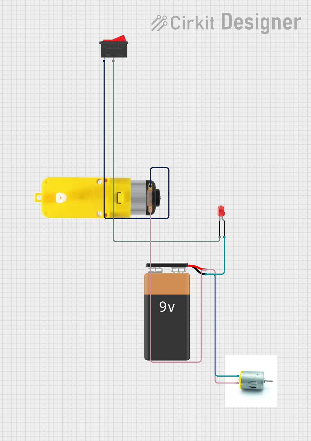
Circuit Documentation
Summary
This document provides a detailed overview of a simple circuit consisting of a 9V battery, a rocker switch, a motor with a reducer, a red LED, and a motor. The circuit is designed to control the motor and LED using the rocker switch. The 9V battery powers the entire circuit.
Component List
9V Battery
- Description: Provides the power supply for the circuit.
- Pins:
+,-
Rocker Switch
- Description: A switch used to control the flow of current in the circuit.
- Pins:
1,2
Motor with Reducer
- Description: A motor with a built-in reducer to control speed.
- Pins:
3 - 6 VCC,GND
LED: Two Pin (red)
- Description: A red LED used as an indicator.
- Pins:
cathode,anode
Motor
- Description: A simple motor.
- Pins:
negative,positive
Wiring Details
9V Battery
Pin
-is connected to:- LED: Two Pin (red)
anode - Motor
negative
- LED: Two Pin (red)
Pin
+is connected to:- Motor with Reducer
GND - Motor
positive
- Motor with Reducer
Rocker Switch
Pin
1is connected to:- Motor with Reducer
3 - 6 VCC
- Motor with Reducer
Pin
2is connected to:- LED: Two Pin (red)
cathode
- LED: Two Pin (red)
Motor with Reducer
Pin
3 - 6 VCCis connected to:- Rocker Switch
1
- Rocker Switch
Pin
GNDis connected to:- 9V Battery
+
- 9V Battery
LED: Two Pin (red)
Pin
cathodeis connected to:- Rocker Switch
2
- Rocker Switch
Pin
anodeis connected to:- 9V Battery
-
- 9V Battery
Motor
Pin
negativeis connected to:- 9V Battery
-
- 9V Battery
Pin
positiveis connected to:- 9V Battery
+
- 9V Battery
Code
There is no microcontroller code associated with this circuit.
This document provides a comprehensive overview of the circuit, including a summary, detailed component list, and wiring details. The circuit is straightforward and does not include any microcontroller code.