Arduino UNO Based Fire Detection and Safety System with Relay-Controlled Water Pump
Circuit Documentation
Summary of the Circuit
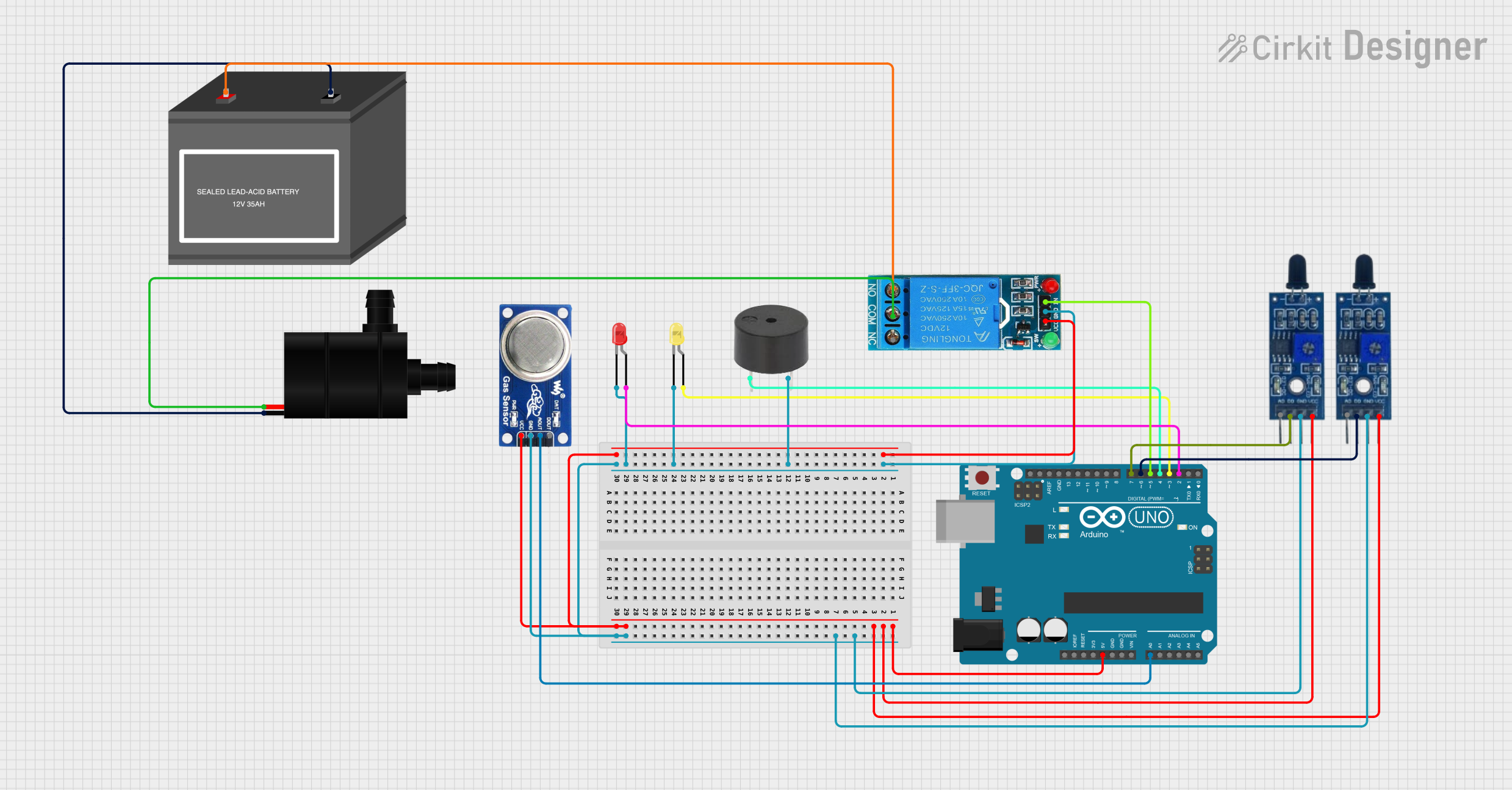
This circuit is designed around an Arduino UNO microcontroller, which serves as the central processing unit for various sensors and actuators. The circuit includes flame sensors for detecting fire, an MQ6 gas sensor for detecting LPG and butane, a buzzer for audible alerts, LEDs for visual indicators, a relay for controlling a water pump, and a 12V battery to power the water pump. The Arduino UNO is responsible for monitoring the sensor inputs and controlling the outputs based on predefined conditions.
Component List
Arduino UNO
- Microcontroller board based on the ATmega328P
- It has 14 digital input/output pins, 6 analog inputs, a 16 MHz quartz crystal, a USB connection, a power jack, an ICSP header, and a reset button.
LED: Two Pin (red)
- A red light-emitting diode (LED) with an anode and cathode for indicating statuses or alerts.
LED: Two Pin (yellow)
- A yellow light-emitting diode (LED) similar to the red LED, used for status indication.
Buzzer
- An electromechanical component that produces a continuous or pulsing sound when a voltage is applied.
12V SINGLE CHANNEL RELAY
- An electrically operated switch that allows you to control a high power circuit with a low power signal.
Flame Sensor (x2)
- A sensor designed to detect the presence of a flame or fire.
MQ6 Gas Sensor
- A sensor for detecting LPG, butane gas, and also useful for gas leakage detecting.
Water Pump
- An electric pump for moving water, typically used in conjunction with the relay to control its operation.
12V Battery (mini)
- A small 12V battery that provides power to the water pump.
Wiring Details
Arduino UNO
- 5V: Powers the flame sensors, MQ6 gas sensor, and the relay module.
- GND: Common ground for the buzzer, yellow and red LEDs, flame sensors, MQ6 gas sensor, and relay module.
- A0: Receives analog input from the MQ6 gas sensor.
- D7: Digital input from one flame sensor.
- D6: Digital input from the other flame sensor.
- D5: Controls the relay module.
- D4: Controls the buzzer.
- D3: Controls the yellow LED.
- D2: Controls the red LED.
LED: Two Pin (red)
- Anode: Connected to D2 on the Arduino UNO.
- Cathode: Connected to GND.
LED: Two Pin (yellow)
- Anode: Connected to D3 on the Arduino UNO.
- Cathode: Connected to GND.
Buzzer
- PIN: Connected to D4 on the Arduino UNO.
- GND: Connected to GND.
12V SINGLE CHANNEL RELAY
- VCC: Powered by 5V from the Arduino UNO.
- GND: Connected to GND.
- IN: Controlled by D5 on the Arduino UNO.
- COM: Connected to the water pump VCC.
- NO: Connected to the positive terminal of the 12V battery.
- NC: Not used in this circuit.
Flame Sensor
- VCC: Powered by 5V from the Arduino UNO.
- GND: Connected to GND.
- D0: One sensor's D0 is connected to D7 on the Arduino UNO, and the other to D6.
MQ6 Gas Sensor
- VCC: Powered by 5V from the Arduino UNO.
- GND: Connected to GND.
- A0: Connected to A0 on the Arduino UNO.
- DO: Not used in this circuit.
Water Pump
- VCC: Connected to the COM pin on the relay module.
- GND: Connected to the negative terminal of the 12V battery.
12V Battery (mini)
- +: Connected to the NO pin on the relay module.
- -: Connected to the GND of the water pump.
Documented Code
void setup() {
  // put your setup code here, to run once:

}

void loop() {
  // put your main code here, to run repeatedly:

}
The provided code is a template with empty setup() and loop() functions. The setup() function is intended for initialization code that runs once when the Arduino is powered on or reset. The loop() function contains the main logic of the program, which runs repeatedly as long as the Arduino is powered.
Further implementation is required to handle sensor readings, control the relay, LEDs, buzzer, and other components based on the sensor inputs.