
ESP32-Based Smart Power Monitoring System with LED Indicators and Piezo Buzzer
View and Edit Project In Cirkit Designer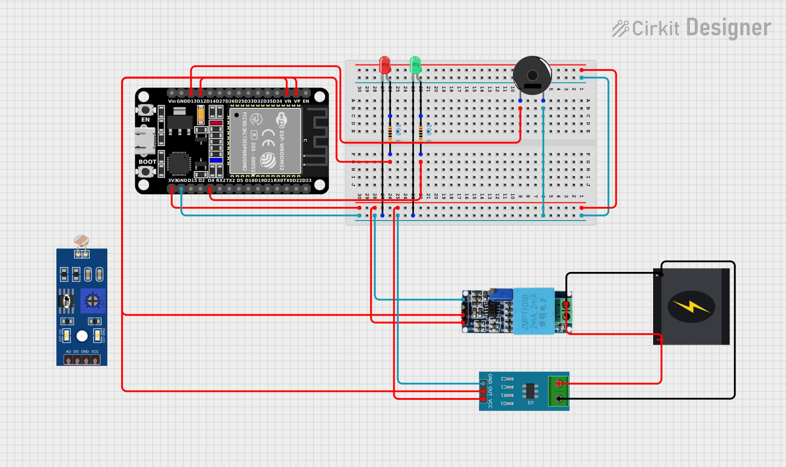
Circuit Documentation
Summary
This document provides a detailed overview of a circuit that includes various sensors, LEDs, a piezo buzzer, resistors, a power source, and an ESP32 microcontroller. The circuit is designed to monitor voltage and current, control LEDs, and produce sound using a piezo buzzer. The ESP32 microcontroller is the central unit that processes sensor data and controls the output devices.
Component List
Voltage Sensor
- Description: Measures the voltage in the circuit.
- Pins: Ground, Phase, Vcc, Out, Gnd
LED: Two Pin (red)
- Description: A red LED used for visual indication.
- Pins: Cathode, Anode
LED: Two Pin (green)
- Description: A green LED used for visual indication.
- Pins: Cathode, Anode
Resistor (200 Ohms)
- Description: Limits the current in the circuit.
- Pins: Pin1, Pin2
- Properties: Resistance: 200 Ohms
240v Power Source
- Description: Provides 240V AC power to the circuit.
- Pins: Live, Neutral
ESP32 (30 pin)
- Description: A microcontroller used for processing and control.
- Pins: EN, VP, VN, D34, D35, D32, D33, D25, D26, D27, D14, D12, D13, GND, Vin, D23, D22, TX0, RX0, D21, D19, D18, D5, TX2, RX2, D4, D2, D15, 3V3
Piezo Buzzer
- Description: Produces sound when activated.
- Pins: Pin 1, Pin 2
Current Sensor 5A
- Description: Measures the current in the circuit.
- Pins: 1, 2, GND, OUT, VCC
LDR
- Description: Light-dependent resistor used to measure light intensity.
- Pins: A0, D0, GND, VCC
Wiring Details
Voltage Sensor
- Ground: Connected to Current Sensor 5A (Pin 1) and 240v Power Source (Neutral)
- Phase: Connected to Current Sensor 5A (Pin 2) and 240v Power Source (Live)
- Vcc: Connected to ESP32 (3V3) and Current Sensor 5A (VCC)
- Out: Connected to ESP32 (VP)
- Gnd: Connected to ESP32 (GND), Piezo Buzzer (Pin 2), LED (red) (Cathode), LED (green) (Cathode), and Current Sensor 5A (GND)
LED: Two Pin (red)
- Cathode: Connected to ESP32 (GND)
- Anode: Connected to Resistor (Pin1)
LED: Two Pin (green)
- Cathode: Connected to ESP32 (GND)
- Anode: Connected to Resistor (Pin1)
Resistor (200 Ohms)
- Pin1: Connected to LED (red) (Anode) and LED (green) (Anode)
- Pin2: Connected to ESP32 (D4) and ESP32 (D12)
240v Power Source
- Live: Connected to Current Sensor 5A (Pin 2) and Voltage Sensor (Phase)
- Neutral: Connected to Current Sensor 5A (Pin 1) and Voltage Sensor (Ground)
ESP32 (30 pin)
- GND: Connected to Voltage Sensor (Gnd), Piezo Buzzer (Pin 2), LED (red) (Cathode), LED (green) (Cathode), and Current Sensor 5A (GND)
- D13: Connected to Piezo Buzzer (Pin 1)
- D4: Connected to Resistor (Pin2)
- D12: Connected to Resistor (Pin2)
- 3V3: Connected to Voltage Sensor (Vcc) and Current Sensor 5A (VCC)
- VN: Connected to Current Sensor 5A (OUT)
- VP: Connected to Voltage Sensor (Out)
Piezo Buzzer
- Pin 1: Connected to ESP32 (D13)
- Pin 2: Connected to ESP32 (GND)
Current Sensor 5A
- 1: Connected to 240v Power Source (Neutral) and Voltage Sensor (Ground)
- 2: Connected to 240v Power Source (Live) and Voltage Sensor (Phase)
- GND: Connected to ESP32 (GND), Piezo Buzzer (Pin 2), LED (red) (Cathode), LED (green) (Cathode), and Voltage Sensor (Gnd)
- OUT: Connected to ESP32 (VN)
- VCC: Connected to ESP32 (3V3) and Voltage Sensor (Vcc)
LDR
- A0: Not connected
- D0: Not connected
- GND: Not connected
- VCC: Not connected
Code
No code is provided for this circuit.
This document provides a comprehensive overview of the circuit, including a summary, component list, wiring details, and code documentation. Each component is described in detail, and the wiring connections are clearly outlined to ensure proper assembly and functionality of the circuit.