
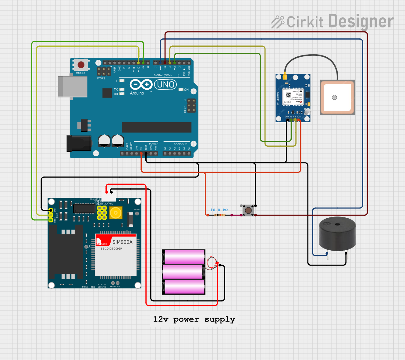
Circuit Documentation
Summary
This circuit is designed to send an SMS alert with GPS coordinates when a pushbutton is pressed. It utilizes an Arduino UNO microcontroller, a SIM900A GSM module, a GPS NEO 6M module, a pushbutton, a buzzer, a resistor, and a 12V battery. The Arduino UNO reads the GPS data and sends an SMS through the GSM module when the button is pressed. The buzzer provides an audible alert when the SMS is sent.
Component List
Arduino UNO
- Description: A microcontroller board based on the ATmega328P.
- Pins: UNUSED, IOREF, Reset, 3.3V, 5V, GND, Vin, A0, A1, A2, A3, A4, A5, SCL, SDA, AREF, D13, D12, D11, D10, D9, D8, D7, D6, D5, D4, D3, D2, D1, D0
SIM900A
- Description: A GSM module used for sending SMS.
- Pins: GND, DB9-3 (RXD), DB9-2 (TXD), 5V, 3VR, 5VR, 3VT, 5VT, VCC, Ring, RESTART, RESET, STATUS
GPS NEO 6M
- Description: A GPS module used for obtaining GPS coordinates.
- Pins: VCC, RX, TX, GND
Pushbutton
- Description: A simple pushbutton used to trigger the SMS alert.
- Pins: Pin 3 (out), Pin 4 (out), Pin 1 (in), Pin 2 (in)
Buzzer
- Description: An audible alert device.
- Pins: PIN, GND
Resistor
- Description: A 10k Ohm resistor.
- Pins: pin1, pin2
- Properties: Resistance: 10k Ohms
Battery 12V
- Description: A 12V battery used to power the GSM module.
- Pins: +, -
Wiring Details
Arduino UNO
- 5V: Connected to Resistor pin1 and GPS NEO 6M VCC
- GND: Connected to SIM900A GND, Pushbutton Pin 1 (in), Buzzer GND, GPS NEO 6M GND, and Battery 12V -
- D10: Connected to SIM900A DB9-3 (RXD)
- D9: Connected to SIM900A DB9-2 (TXD)
- D6: Connected to Buzzer PIN
- D5: Connected to Pushbutton Pin 3 (out)
- D4: Connected to GPS NEO 6M RX
- D3: Connected to GPS NEO 6M TX
SIM900A
- GND: Connected to Arduino UNO GND and Battery 12V -
- DB9-3 (RXD): Connected to Arduino UNO D10
- DB9-2 (TXD): Connected to Arduino UNO D9
- 5V: Connected to Battery 12V +
GPS NEO 6M
- VCC: Connected to Arduino UNO 5V
- RX: Connected to Arduino UNO D4
- TX: Connected to Arduino UNO D3
- GND: Connected to Arduino UNO GND
Pushbutton
- Pin 1 (in): Connected to Arduino UNO GND
- Pin 3 (out): Connected to Arduino UNO D5
- Pin 4 (out): Connected to Resistor pin2
Buzzer
- PIN: Connected to Arduino UNO D6
- GND: Connected to Arduino UNO GND
Resistor
- pin1: Connected to Arduino UNO 5V
- pin2: Connected to Pushbutton Pin 4 (out)
Battery 12V
- +: Connected to SIM900A 5V
- -: Connected to Arduino UNO GND and SIM900A GND
Code Documentation
#include <TinyGPS.h>
#include <SoftwareSerial.h>

SoftwareSerial Gsm(9, 10); // GSM module connections
SoftwareSerial GPS(3, 4);  // GPS module connections

TinyGPS gps;
char phone_no[] = "+91883058xxxx"; // Replace with your phone number
const int buttonPin = 5;
const int buzzerPin = 6;
bool isSMSsent = false;

void setup() {
  Serial.begin(9600);
  Gsm.begin(9600);
  GPS.begin(9600);

  sendATCommand("AT+CMGF=1\r", 1000); // Set SMS to text mode
  sendATCommand("AT+CNMI=2,2,0,0,0\r", 1000); // Enable SMS notifications

  pinMode(buttonPin, INPUT_PULLUP);
  pinMode(buzzerPin, OUTPUT);
}

void loop() {
  GPS.listen();
  readGPSData();

  checkButtonAndSendSMS();
}

void readGPSData() {
  while (GPS.available()) {
    if (gps.encode(GPS.read())) {
      // Successfully encoded GPS data
    }
  }
}

void checkButtonAndSendSMS() {
  if (digitalRead(buttonPin) == LOW && !isSMSsent) {
    isSMSsent = true;

    float flat, flon;
    gps.f_get_position(&flat, &flon);

    Gsm.listen();
    sendSMS(flat, flon);
  } else if (digitalRead(buttonPin) == HIGH) {
    isSMSsent = false;
  }
}

void sendATCommand(String command, int timeout) {
  Gsm.println(command);
  unsigned long startTime = millis();

  while (millis() - startTime < timeout) {
    if (Gsm.find("OK")) {
      return; // Command successful
    }
    if (Gsm.find("ERROR")) {
      Serial.println("AT Command Error!");
      return; // Command failed
    }
  }
  Serial.println("AT Command Timeout!");
}

void sendSMS(float flat, float flon) {
  Gsm.print("AT+CMGS=\"");
  Gsm.print(phone_no);
  Gsm.println("\"\r");
  delay(100);

  Gsm.println("Alert! I need help at:");
  Gsm.print("Latitude: ");
  Gsm.println(flat == TinyGPS::GPS_INVALID_F_ANGLE ? "N/A" : String(flat, 6));
  Gsm.print("Longitude: ");
  Gsm.println(flon == TinyGPS::GPS_INVALID_F_ANGLE ? "N/A" : String(flon, 6));
  Gsm.print("http://maps.google.com/maps?q=loc:");
  Gsm.print(flat == TinyGPS::GPS_INVALID_F_ANGLE ? 0.0 : flat, 6);
  Gsm.print(",");
  Gsm.println(flon == TinyGPS::GPS_INVALID_F_ANGLE ? 0.0 : flon, 6);

  delay(100);
  Gsm.println((char)26); // Send SMS
  delay(100);

  if (Gsm.find("OK")) {
    Serial.println("SMS Sent!");
    digitalWrite(buzzerPin, HIGH);
    delay(1000);
    digitalWrite(buzzerPin, LOW);
  } else {
    Serial.println("SMS Send Failed!");
  }
}
This code initializes the GSM and GPS modules, reads GPS data, and sends an SMS with the GPS coordinates when the pushbutton is pressed. The buzzer provides an audible alert when the SMS is successfully sent.