
433 MHz RF Transmitter and Receiver with Arduino Uno for Wireless LED Control
View and Edit Project In Cirkit Designer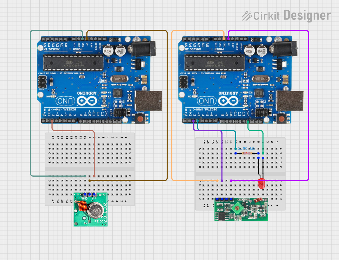
Circuit Documentation
Summary
This circuit involves two Arduino Uno R3 microcontrollers, a 433 MHz RF Receiver Module, an FS1000A 433MHz RF Transmitter, a red LED, and a 1k Ohm resistor. The circuit is designed to transmit and receive data wirelessly using the 433 MHz frequency. The transmitter sends a "Hello" message every 200ms, and the receiver turns on an LED when it successfully receives a message.
Component List
433 MHz RF Receiver Module
- Description: A module used to receive data transmitted at 433 MHz.
- Pins: VCC, DATA, GND
Arduino Uno R3
- Description: A microcontroller board based on the ATmega328P.
- Pins: D8, D9, D10, D11, D12, D13, GND, AREF, SDA, SCL, D0/RX, D1/Tx, D2, D3, D4, D5, 6, D7, A5/SCL, A4/SDA, A3, A2, A1, A0, Vin, 5V, 3.3V, RESET, IOREF, NONE, USB Jack, Power Jack
Resistor
- Description: A passive electrical component that implements electrical resistance as a circuit element.
- Pins: pin1, pin2
- Properties:
- Resistance: 1000 Ohms
LED: Two Pin (red)
- Description: A light-emitting diode that emits red light.
- Pins: cathode, anode
FS1000A 433MHz RF Transmitter
- Description: A module used to transmit data at 433 MHz.
- Pins: DATA, VCC, GND, ANT
Wiring Details
433 MHz RF Receiver Module
- VCC connected to Arduino Uno R3 (5V)
- DATA connected to Arduino Uno R3 (D2)
- GND connected to Arduino Uno R3 (GND)
Arduino Uno R3 (Receiver)
- D2 connected to 433 MHz RF Receiver Module (DATA)
- 5V connected to 433 MHz RF Receiver Module (VCC)
- GND connected to 433 MHz RF Receiver Module (GND)
- D3 connected to Resistor (pin1)
- GND connected to LED (cathode)
Resistor
- pin1 connected to Arduino Uno R3 (D3)
- pin2 connected to LED (anode)
LED: Two Pin (red)
- cathode connected to Arduino Uno R3 (GND)
- anode connected to Resistor (pin2)
FS1000A 433MHz RF Transmitter
- DATA connected to Arduino Uno R3 (D2)
- VCC connected to Arduino Uno R3 (5V)
- GND connected to Arduino Uno R3 (GND)
Arduino Uno R3 (Transmitter)
- D2 connected to FS1000A 433MHz RF Transmitter (DATA)
- 5V connected to FS1000A 433MHz RF Transmitter (VCC)
- GND connected to FS1000A 433MHz RF Transmitter (GND)
Code Documentation
Arduino Uno R3 (Receiver)
#include <VirtualWire.h>

void setup() {
  pinMode(3, OUTPUT); // Set pin for LED
  vw_set_rx_pin(2);   // Set the RX pin
  vw_setup(2000);     // Bits per second
  vw_rx_start();      // Start the receiver
}

void loop() {
  uint8_t buf[VW_MAX_MESSAGE_LEN];
  uint8_t buflen = VW_MAX_MESSAGE_LEN;

  if (vw_get_message(buf, &buflen)) { // Non-blocking
    digitalWrite(3, HIGH); // Turn on LED
  } else {
    digitalWrite(3, LOW); // Turn off LED
  }
}
Arduino Uno R3 (Transmitter)
#include <VirtualWire.h>

void setup() {
  vw_set_tx_pin(2); // Set the TX pin
  vw_setup(2000);   // Bits per second
}

void loop() {
  const char *msg = "Hello";
  vw_send((uint8_t *)msg, strlen(msg));
  vw_wait_tx(); // Wait until the message is sent
  delay(200);   // Send message every 200ms
}