
IR Sensor-Controlled Relay Switch for AC Bulb with Battery Backup
View and Edit Project In Cirkit Designer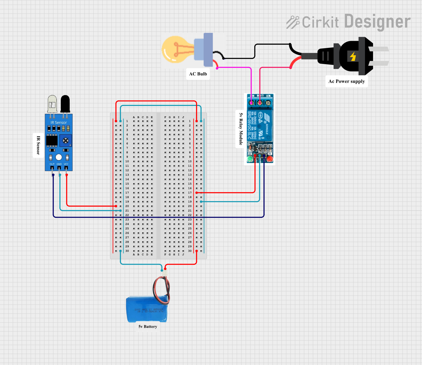
Circuit Documentation
Summary
This circuit is designed to control an AC-powered bulb using a 5V relay and an IR sensor. The IR sensor detects motion and triggers the relay, which in turn controls the AC power to the bulb. The circuit is powered by a 5V battery.
Component List
5V Relay
- Pins: Normally Open, Common terminal, Normally Closed, In, GND, VCC
- Description: A relay that operates at 5V to control high voltage AC loads.
- Purpose: To switch the AC power to the bulb based on the signal from the IR sensor.
5V Battery
- Pins: positive, negative
- Description: A 5V power source.
- Purpose: To provide power to the relay and the IR sensor.
IR Sensor
- Pins: out, gnd, vcc
- Description: An infrared sensor that detects motion.
- Purpose: To detect motion and send a signal to the relay.
Bulb
- Pins: GND, power
- Description: An AC-powered bulb.
- Purpose: To provide illumination when the relay is activated.
AC Source
- Pins: +, -
- Description: An AC power source.
- Purpose: To provide AC power to the bulb through the relay.
Comment
- Pins: None
- Description: Placeholder for comments.
- Purpose: Not used in the circuit.
Wiring Details
5V Relay
- VCC: Connected to the positive pin of the 5V battery and the vcc pin of the IR sensor.
- GND: Connected to the negative pin of the 5V battery and the gnd pin of the IR sensor.
- In: Connected to the out pin of the IR sensor.
- Common terminal: Connected to the + pin of the AC source.
- Normally Closed: Connected to the power pin of the bulb.
5V Battery
- positive: Connected to the VCC pin of the 5V relay and the vcc pin of the IR sensor.
- negative: Connected to the GND pin of the 5V relay and the gnd pin of the IR sensor.
IR Sensor
- vcc: Connected to the positive pin of the 5V battery and the VCC pin of the 5V relay.
- gnd: Connected to the negative pin of the 5V battery and the GND pin of the 5V relay.
- out: Connected to the In pin of the 5V relay.
Bulb
- power: Connected to the Normally Closed pin of the 5V relay.
- GND: Connected to the - pin of the AC source.
AC Source
- +: Connected to the Common terminal pin of the 5V relay.
- -: Connected to the GND pin of the bulb.
Code
No microcontroller code is provided for this circuit.