Cirkit Designer
Your all-in-one circuit design IDE
Home /
Project Documentation
Arduino Nano Based GPS Tracker with GSM Communication
Circuit Documentation
Summary of the Circuit
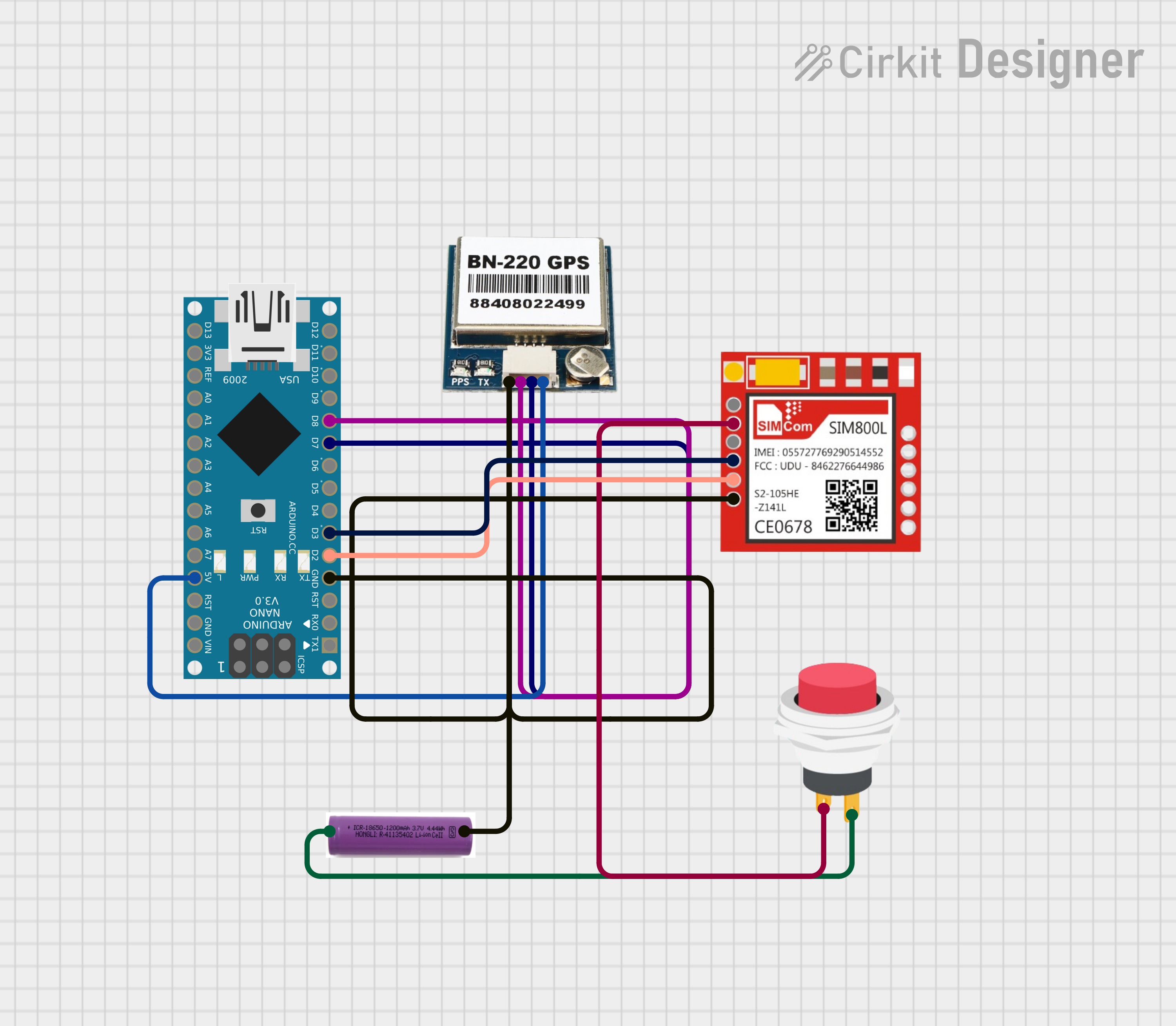
This circuit integrates a GPS module (BN-220 GPS), a GSM module (Sim800l), and an Arduino Nano microcontroller to create a system capable of receiving GPS coordinates and communicating via GSM. The system is powered by a 3.7V battery and includes a 2-pin push switch to control the power supply to the GSM module. The Arduino Nano is programmed to interpret GPS data, control a relay based on received text messages, and send location data via SMS.
Component List
BN-220 GPS
- Pins: GND, TX, RX, VCC
- Description: A GPS module that provides location data.
Sim800l
- Pins: NET, RST, VCC, RXD, TXD, GND
- Description: A GSM/GPRS module for cellular communication.
Arduino Nano
- Pins: D1/TX, D0/RX, RESET, GND, D2 to D13, VIN, 5V, A0 to A7, AREF, 3V3
- Description: A compact microcontroller board based on the ATmega328P.
3.7V Battery
- Pins: +, -
- Description: A power source for the circuit.
2-Pin Push Switch
- Pins: Input +, Output +
- Description: A switch to control the power supply to the GSM module.
Wiring Details
BN-220 GPS
- GND connected to the common ground.
- TX connected to Arduino Nano's D8.
- RX connected to Arduino Nano's D7.
- VCC connected to Arduino Nano's 5V.
Sim800l
- GND connected to the common ground.
- VCC connected through the 2-Pin Push Switch.
- RXD connected to Arduino Nano's D3.
- TXD connected to Arduino Nano's D2.
Arduino Nano
- GND connected to the common ground.
- D8 connected to BN-220 GPS TX.
- D7 connected to BN-220 GPS RX.
- 5V connected to BN-220 GPS VCC.
- D3 connected to Sim800l RXD.
- D2 connected to Sim800l TXD.
3.7V Battery
- + connected to the 2-Pin Push Switch Input +.
- - connected to the common ground.
2-Pin Push Switch
- Input + connected to the 3.7V Battery +.
- Output + connected to Sim800l VCC.
Documented Code
The following code is written for the Arduino Nano to control the GPS and GSM modules:
#include <TinyGPS++.h>
#include <SoftwareSerial.h>

SoftwareSerial GSM(2, 3); // RX, TX
SoftwareSerial neo(8, 7); // RX, TX
String textMessage;
String lampState;
String lati = "";
String longi = "";
int led = 13;
const int relay = 12;
TinyGPSPlus gps;

void setup() {
  pinMode(led, OUTPUT);
  pinMode(relay, OUTPUT);
  digitalWrite(relay, HIGH);
  Serial.begin(9600);
  GSM.begin(9600);
  neo.begin(9600);
  GSM.listen();
  delay(5000);
  digitalWrite(led, HIGH);
  Serial.print("GSM ready...\r\n");
  GSM.print("AT+CMGF=1\r\n");
  delay(1000);
  GSM.print("AT+CNMI=2,2,0,0,0\r\n");
  delay(1000);
  digitalWrite(led, LOW);
}

void loop() {
  GSM.listen();
  delay(2);
  while (GSM.available() > 0) {
    digitalWrite(led, HIGH);
    textMessage = GSM.readString();
    Serial.print(textMessage);
    delay(10);
    digitalWrite(led, LOW);
  }
  neo.listen();
  if (textMessage.indexOf("ON") >= 0) {
    digitalWrite(relay, LOW);
    lampState = "ON";
    Serial.println("Bike set to ON\r\n");
    textMessage = "";
    GSM.println("AT+CMGS=\"+9188305848xx\"");
    delay(500);
    GSM.print("Bike set to ON\r");
    GSM.write(0x1a);
    delay(1000);
    GSM.println("AT+CMGD=1,4");
  }
  if (textMessage.indexOf("OFF") >= 0) {
    digitalWrite(relay, HIGH);
    lampState = "OFF";
    Serial.println("Bike set to OFF\r\n");
    textMessage = "";
    GSM.println("AT+CMGS=\"+9188305848xx\"");
    delay(500);
    GSM.print("Bike set to OFF\r");
    GSM.write(0x1a);
    delay(1000);
    GSM.println("AT+CMGD=1,4");
  }
  if (textMessage.indexOf("GETLOC") >= 0) {
    smartDelay(1000);
    Serial.println("GPS data Received\r\n");
    textMessage = "";
    GSM.println("AT+CMGS=\"+9188305848xx\"");
    delay(500);
    String pesan = "https://maps.google.com/?q=" + lati + "," + longi;
    GSM.print(pesan);
    GSM.write(0x1a);
    delay(1000);
    GSM.println("AT+CMGD=1,4");
  }
}

static void smartDelay(unsigned long ms) {
  unsigned long start = millis();
  do {
    delay(2);
    while (neo.available())
      gps.encode(neo.read());
  } while (millis() - start < ms);
  lati = String(gps.location.lat(), 8);
  longi = String(gps.location.lng(), 6);
  Serial.println(lati);
  Serial.println(longi);
}
This code initializes the GSM and GPS modules, listens for incoming SMS messages, and controls a relay based on the content of the messages. It also sends the GPS location when requested via SMS.