Cirkit Designer
Your all-in-one circuit design IDE
Home /
Project Documentation
Arduino UNO Controlled LED Dimmer
Circuit Documentation
Summary of the Circuit
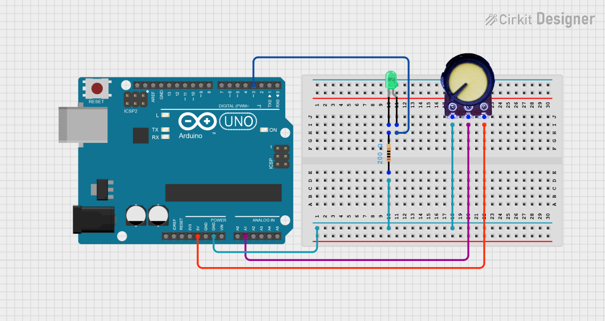
This circuit is designed around an Arduino UNO microcontroller, which serves as the central processing unit. The circuit includes a green LED, a resistor, and a potentiometer. The LED is controlled by the Arduino through a digital pin, with the brightness potentially being modulated by the potentiometer. The resistor is used to limit the current through the LED to prevent damage. The potentiometer can be used to adjust the voltage input to an analog pin on the Arduino, which could be used in the code to affect the LED's behavior or for other input purposes.
Component List
Arduino UNO
- Description: A microcontroller board based on the ATmega328P.
- Pins: UNUSED, IOREF, Reset, 3.3V, 5V, GND, Vin, A0-A5, SCL, SDA, AREF, D0-D13
LED: Two Pin (green)
- Description: A basic green light-emitting diode.
- Pins: cathode, anode
Resistor
- Description: A passive two-terminal electrical component that implements electrical resistance as a circuit element.
- Resistance: 200 Ohms
- Pins: pin1, pin2
Potentiometer
- Description: A three-terminal resistor with a sliding or rotating contact that forms an adjustable voltage divider.
- Pins: GND, Output, VCC
Wiring Details
Arduino UNO
- GND connected to Resistor (pin1) and Potentiometer (GND)
- D3 connected to LED (anode)
- A1 connected to Potentiometer (Output)
- 5V connected to Potentiometer (VCC)
LED: Two Pin (green)
- anode connected to Arduino UNO (D3)
- cathode connected to Resistor (pin2)
Resistor
- pin1 connected to Arduino UNO (GND)
- pin2 connected to LED (cathode)
Potentiometer
- GND connected to Arduino UNO (GND)
- Output connected to Arduino UNO (A1)
- VCC connected to Arduino UNO (5V)
Documented Code
Arduino UNO Code (sketch.ino)
void setup() {
  // put your setup code here, to run once:

}

void loop() {
  // put your main code here, to run repeatedly:

}
Additional Notes (documentation.txt)
No additional code documentation was provided.