
Arduino Mega 2560 Based Automated Irrigation System with Soil Moisture Sensing and LCD Display
View and Edit Project In Cirkit Designer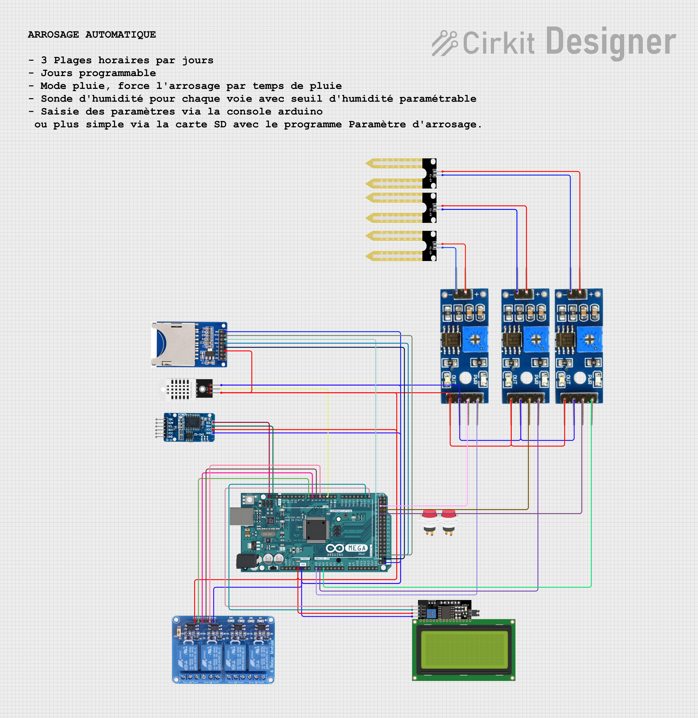
Circuit Documentation
Summary
This circuit is designed to automate a garden watering system. It includes an Arduino Mega 2560 microcontroller to manage inputs from soil moisture sensors and a DHT22 temperature/humidity sensor, control a 4-channel relay connected to water valves, and interface with an LCD display and an SD card reader for user interaction and configuration. The system allows for scheduling watering times, adjusting moisture thresholds, and can operate the valves even during rainfall if configured to do so.
Component List
Arduino Mega 2560
- Microcontroller board based on the ATmega2560
- It has 54 digital input/output pins (of which 15 can be used as PWM outputs), 16 analog inputs, 4 UARTs (hardware serial ports), a 16 MHz crystal oscillator, a USB connection, a power jack, an ICSP header, and a reset button.
SD Card Reader (2 Pins)
- A module that allows reading and writing to an SD card using the SPI communication protocol.
- It typically includes pins for power supply, ground, chip select (CS), Master Out Slave In (MOSI), Master In Slave Out (MISO), and Serial Clock (SCK).
LCD Display 20x4 I2C
- A 20x4 character LCD display with an I2C interface for displaying text and numbers.
- It simplifies the connection to the microcontroller by using just two data lines (SDA and SCL).
DHT22
- A sensor for measuring temperature and humidity.
- It has a digital output and requires a single data line for communication with the microcontroller.
Relay 4 Channel 5V
- A module with 4 relays that can be controlled independently to switch high voltage/current loads.
- Each relay has a set of Common (COM), Normally Open (NO), and Normally Closed (NC) contacts.
Soil Moisture Module (3 instances)
- A sensor module used to measure the moisture level in the soil.
- It typically includes both analog and digital outputs to interface with the microcontroller.
RTC DS3231
- A real-time clock module that maintains accurate timekeeping even when the main microcontroller is powered off.
- It communicates with the microcontroller via I2C.
YL-69 Sonda (3 instances)
- A probe that works in conjunction with the soil moisture module to detect the moisture content in the soil.
2Pin Push Switch (2 instances)
- A simple push-button switch that can be used to trigger events or reset states in the circuit.
Comment
- A placeholder for additional notes or comments within the circuit design.
Wiring Details
Power Supply Connections
- The 5V and GND pins of the Arduino Mega 2560 are connected to the VCC and GND pins of the DHT22, LCD Display, Soil Moisture Modules, SD Card Reader, Relay Module, and RTC DS3231 to provide power.
Soil Moisture Modules
- The analog output pins of the Soil Moisture Modules are connected to the A0, A1, and A2 analog input pins of the Arduino Mega 2560 for moisture level readings.
- The digital output pins of the Soil Moisture Modules are connected to the D24, D26, and D28 digital pins of the Arduino Mega 2560 for digital moisture level readings.
LCD Display 20x4 I2C
- The SCL and SDA pins of the LCD Display are connected to the D21/SCL and D20/SDA pins of the Arduino Mega 2560 for I2C communication.
DHT22
- The Out pin of the DHT22 is connected to the D2 PWM pin of the Arduino Mega 2560 for data communication.
Relay 4 Channel 5V
- The IN1, IN2, IN3, and IN4 input pins of the Relay Module are connected to the D4 PWM, D5 PWM, D6 PWM, and D7 PWM pins of the Arduino Mega 2560 to control the relays.
RTC DS3231
- The SCL and SDA pins of the RTC DS3231 are connected to the SCL and SDA pins of the Arduino Mega 2560 for I2C communication.
SD Card Reader
- The CS, MOSI, MISO, and SCK pins of the SD Card Reader are connected to the D53, D51, D50, and D52 pins of the Arduino Mega 2560 for SPI communication.
YL-69 Sonda
- The probes are connected to the corresponding positive and negative pins of the Soil Moisture Modules to measure the soil moisture content.
2Pin Push Switch
- The push switches are not detailed in the net list, suggesting they may be used for user input or reset functionality, and would typically be connected to a digital pin and ground.
Documented Code
The code for the Arduino Mega 2560 is written in C++ and is designed to control the garden watering system. It includes libraries for interfacing with the RTC, DHT sensor, LCD display, and SD card. The code initializes the components, reads sensor data, and controls the relays based on the time, soil moisture, and user-defined settings. It also includes a menu system for user interaction via the serial monitor and functions for reading and writing configuration settings to the SD card.
The code is too extensive to include in this document fully, but here is a brief overview of its structure:
- Libraries: The code includes necessary libraries for the RTC, DHT sensor, LCD, and SD card.
- Pin Definitions: Defines the pins used for the DHT sensor, relays, soil moisture sensors, and SD card.
- Global Variables: Declares variables for storing sensor readings, configuration settings, and state flags.
- Setup Function: Initializes the serial communication, RTC, DHT sensor, LCD, SD card, and configures the pin modes.
- Loop Function: Contains the main program logic that checks the current time, reads sensor data, interacts with the user, and controls the relays based on the configuration.
- Helper Functions: Includes functions for reading the temperature and humidity, controlling the pump, interacting with the user, reading and writing configuration settings, and checking the watering schedule.
The code is well-commented, providing explanations for each section and its functionality. It also includes error handling for the RTC and SD card initialization.