
Circuit Documentation
Summary of the Circuit
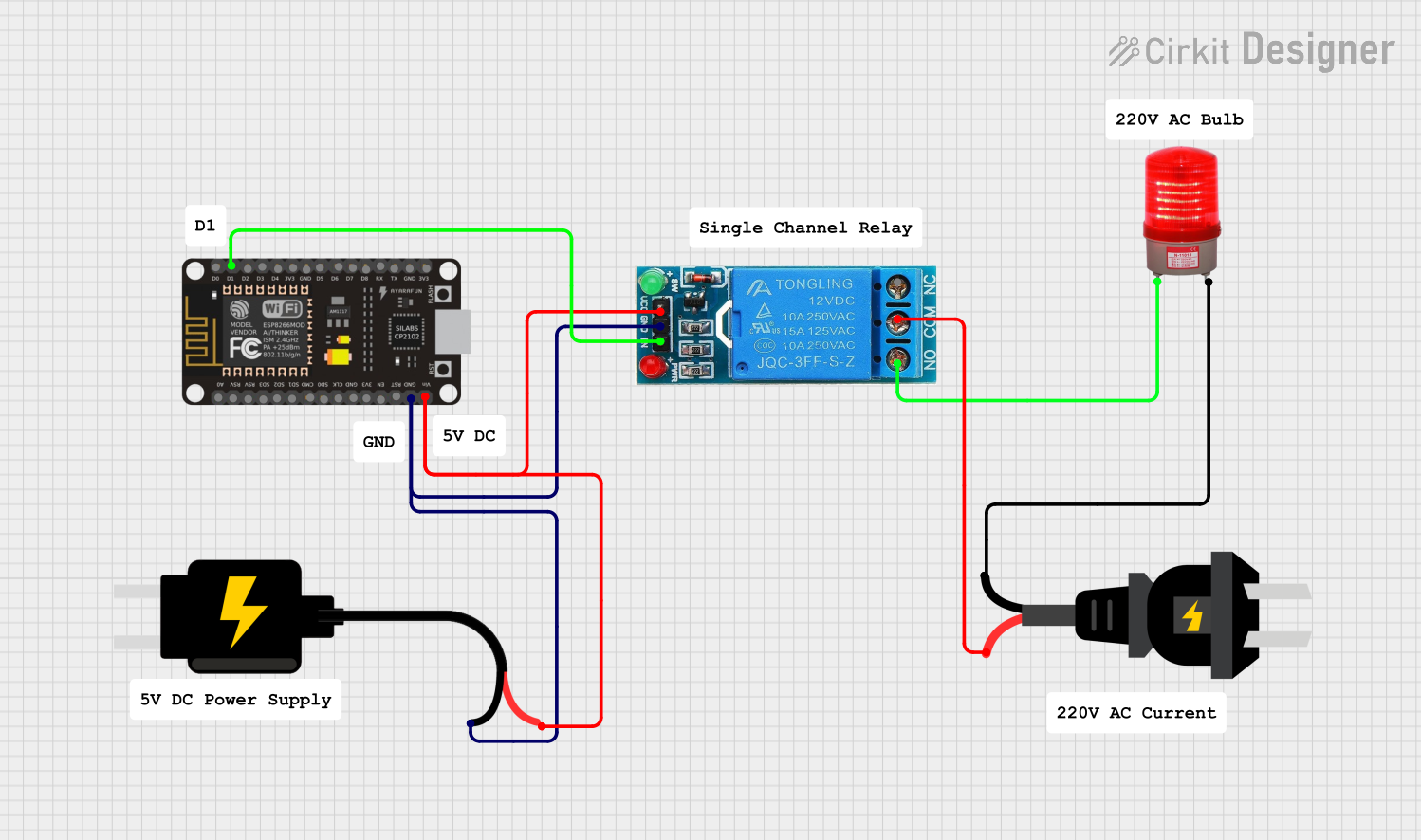
The circuit described by the provided inputs consists of a 12V single-channel relay module controlled by an ESP8266 NodeMCU microcontroller. The relay module is used to switch a red light that operates at 220VAC. The ESP8266 NodeMCU is powered by a 5V DC source, which also supplies power to the relay module. The relay's control input (IN) is connected to one of the digital pins (D1) of the ESP8266 NodeMCU, allowing the microcontroller to control the state of the relay. The ground connections of the relay, microcontroller, and DC source are all tied together, forming a common ground for the circuit. The AC source provides the 220VAC needed for the red light and is connected to the common terminal (COM) of the relay, while the normally open (NO) terminal of the relay is connected to the red light. This setup allows the microcontroller to control the power to the red light via the relay.
Component List
12V Single Channel Relay
- Description: A relay module capable of switching higher voltage and current loads using a low voltage control signal.
- Pins: NC (Normally Closed), COM (Common), NO (Normally Open), IN (Input), GND (Ground), VCC (Voltage Supply)
ESP8266 NodeMCU
- Description: A microcontroller board based on the ESP8266 Wi-Fi SoC, with digital I/O pins and a single analog input.
- Pins: D0, D1, D2, D3, D4, 3V3, GND, D5, D6, D7, D8, RX, TX, A0, RSV, SD3, SD2, SD1, CMD, SD0, CLK, EN, RST, VIN
DC Source 5V
- Description: A power supply module that provides a regulated 5V DC output.
- Pins: VCC, GND
Red Light 220VAC
- Description: An indicator light that operates at 220VAC.
- Pins: -, +
AC Source
- Description: A source of alternating current, providing 220VAC for the circuit.
- Pins: -, +
Wiring Details
12V Single Channel Relay
- COM connected to AC source (-)
- NO connected to red light 220VAC (+)
- IN connected to ESP8266 NodeMCU (D1)
- GND connected to common ground
- VCC connected to 5V DC source (VCC)
ESP8266 NodeMCU
- D1 connected to 12V Single Channel Relay (IN)
- GND connected to common ground
- VIN connected to 5V DC source (VCC)
DC Source 5V
- VCC connected to ESP8266 NodeMCU (VIN) and 12V Single Channel Relay (VCC)
- GND connected to common ground
Red Light 220VAC
- + connected to 12V Single Channel Relay (NO)
- - connected to AC source (+)
AC Source
- + connected to red light 220VAC (-)
- - connected to 12V Single Channel Relay (COM)
Documented Code
There is no code provided for the microcontroller in this circuit. If code is later provided, it should be documented here, including descriptions of what each section of the code is intended to do, any libraries used, and the logic behind the code's operation.