Cirkit Designer
Your all-in-one circuit design IDE
Home /
Project Documentation
Arduino-Controlled Multi-Touch Sensor Interface with Solar Charging and OLED Display
Circuit Documentation
Summary
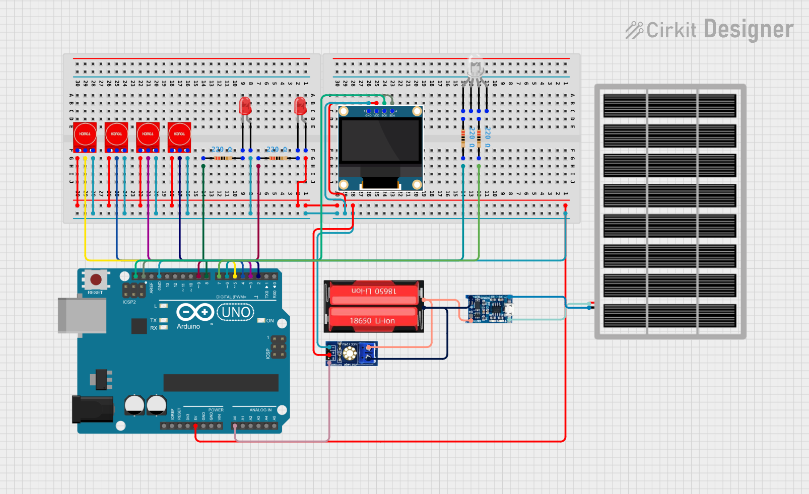
This circuit integrates various components including touch sensors, LEDs, resistors, a solar panel, a Li-Ion battery, a charging module, an Arduino UNO microcontroller, a common cathode RGB LED, an OLED display, and a voltage sensor. The circuit is designed to interact with touch inputs, display information on an OLED screen, and control LED states. It is powered by a solar panel that charges a Li-Ion battery, which in turn powers the circuit. The Arduino UNO serves as the central processing unit, interfacing with the touch sensors, OLED display, and voltage sensor to perform the desired functions.
Component List
Touch Sensor TTP233
- Description: Capacitive touch sensor module.
- Pins: GND, I/O, VCC
LED: Two Pin (red)
- Description: Red light-emitting diode.
- Pins: cathode, anode
Resistor
- Description: Passive electrical component with a specific resistance value.
- Properties: Resistance - 220 Ohms
Solar Panel
- Description: Photovoltaic panel for converting solar energy into electrical power.
- Pins: gnd, vcc
18650 Li-Ion Battery
- Description: Rechargeable lithium-ion battery.
- Pins: Positive, Negative
TP4056 Charging Module
- Description: Lithium battery charging module.
- Pins: (Not specified)
Arduino UNO
- Description: Microcontroller board based on the ATmega328P.
- Pins: UNUSED, IOREF, Reset, 3.3V, 5V, GND, Vin, A0-A5, SCL, SDA, AREF, D0-D13
LED: Four Pin (Common Cathode)
- Description: RGB LED with a common cathode.
- Pins: red anode, common cathode, green anode, blue anode
0.96" OLED
- Description: Small OLED display for visual output.
- Pins: GND, VDD, SCK, SDA
Voltage Sensor DC
- Description: Module for sensing DC voltage levels.
- Pins: signal, vcc, gnd, GND, VCC
Wiring Details
Touch Sensor TTP233
- GND: Connected to the common ground net.
- I/O: Connected to individual digital pins (D2, D3, D4, D5) on the Arduino UNO.
- VCC: Connected to the common 5V net.
LED: Two Pin (red)
- cathode: Connected to the corresponding resistor (pin2).
- anode: Connected to the common 5V net.
Resistor (220 Ohms)
- pin1: Connected to the corresponding LED anode or Arduino digital pins (D8, D9) or RGB LED anode.
- pin2: Connected to the corresponding LED cathode or Arduino digital pins (D6, D7).
Solar Panel
- gnd: Connected to the TP4056 charging module.
- vcc: Connected to the TP4056 charging module.
18650 Li-Ion Battery
- Positive: Connected to the TP4056 charging module and voltage sensor DC VCC.
- Negative: Connected to the TP4056 charging module and voltage sensor DC GND.
TP4056 Charging Module
- Connections to the solar panel and 18650 Li-Ion battery.
Arduino UNO
- 5V: Connected to the common 5V net.
- GND: Connected to the common ground net.
- Digital Pins (D2-D9): Connected to touch sensors I/O and resistors.
- Analog Pin (A0): Connected to the voltage sensor DC signal.
- SDA: Connected to the OLED SDA.
- SCL: Connected to the OLED SCK.
LED: Four Pin (Common Cathode)
- red anode: Connected to a 220 Ohm resistor (pin1).
- green anode: Connected to a 220 Ohm resistor (pin1).
- common cathode: (Connection details not provided)
0.96" OLED
- GND: Connected to the common ground net.
- VDD: Connected to the common 5V net.
- SCK: Connected to the Arduino UNO SCL.
- SDA: Connected to the Arduino UNO SDA.
Voltage Sensor DC
- signal: Connected to the Arduino UNO A0.
- vcc: Connected to the 18650 Li-Ion battery Positive.
- gnd: Connected to the 18650 Li-Ion battery Negative.
Documented Code
Arduino UNO Code (sketch.ino)
void setup() {
  // put your setup code here, to run once:

}

void loop() {
  // put your main code here, to run repeatedly:

}
Additional Notes
- The provided code is a template and does not contain any functional code specific to the circuit's operation.
- Further implementation is required to handle input from the touch sensors, control the LEDs, read from the voltage sensor, and display data on the OLED screen.
- The code should be expanded to include pin mode declarations, touch sensor reading, LED state control, voltage sensing, and OLED display updates.