
Circuit Documentation
Summary
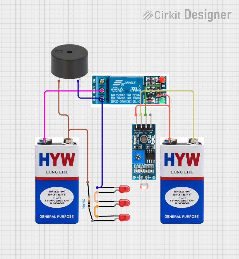
The circuit in question appears to be a simple control circuit that utilizes a 5V relay to switch between a buzzer and a series of LEDs based on the output of a Module LDR (Light Dependent Resistor). The circuit is powered by two separate 9V batteries, which suggests that different parts of the circuit may operate at different voltage levels or require isolation. The relay is likely controlled by the digital output (DO) of the LDR module, which changes state based on the ambient light level detected by the LDR sensor.
Component List
5V Relay
- Description: A relay is an electrically operated switch that allows you to control a high-power circuit with a low-power signal.
- Pins: Normally Open, Common terminal, Normally Closed, In, GND, VCC
Module LDR
- Description: An LDR module contains a light-dependent resistor and typically provides both analog and digital outputs.
- Pins: VCC, GND, DO, AO
9V Battery
- Description: A standard 9V battery used to provide power to the circuit.
- Pins: +, -
LED: Two Pin (red)
- Description: A basic red LED used as an indicator or for illumination.
- Pins: cathode, anode
Buzzer
- Description: An electromechanical component that emits sound when energized.
- Pins: PIN, GND
Resistor
- Description: A passive two-terminal electrical component that implements electrical resistance as a circuit element.
- Pins: pin1, pin2
- Properties: Resistance (Value not specified)
Wiring Details
5V Relay
- Common terminal connected to the positive terminal of a 9V battery.
- Normally Closed connected to the cathode of an LED and the GND of a buzzer.
- In connected to the DO pin of the Module LDR.
- GND connected to the GND pin of the Module LDR and the negative terminal of a 9V battery.
- VCC connected to the VCC pin of the Module LDR and the positive terminal of a 9V battery.
Module LDR
- VCC connected to the positive terminal of a 9V battery and the VCC of the 5V relay.
- GND connected to the negative terminal of a 9V battery and the GND of the 5V relay.
- DO connected to the In pin of the 5V relay.
9V Battery
- + connected to the Common terminal of the 5V relay and the VCC of the Module LDR.
- - connected to the GND of the Module LDR and the GND of the 5V relay.
LED: Two Pin (red)
- cathode of one LED connected to the Normally Closed pin of the 5V relay and the GND of the buzzer.
- anode of one LED connected to the cathode of another LED.
Buzzer
- PIN connected to the negative terminal of a 9V battery through a resistor.
- GND connected to the Normally Closed pin of the 5V relay.
Resistor
- pin2 connected to the PIN of the buzzer.
- pin1 (not specified in the net list, likely connected to the negative terminal of a 9V battery).
Documented Code
No code has been provided for any microcontrollers in the circuit. If the circuit is intended to be controlled by a microcontroller, the code would be necessary to define the behavior of the microcontroller's outputs based on sensor inputs or other conditions. Since no code is present, it is assumed that the circuit operates purely on the hardware level, with the LDR module directly controlling the state of the relay.
Please note that the documentation above is based on the provided parts list and electrical net list. If there are any additional requirements or specific functionalities not captured by the provided information, further details would be needed to complete the documentation.