
Circuit Documentation
Summary
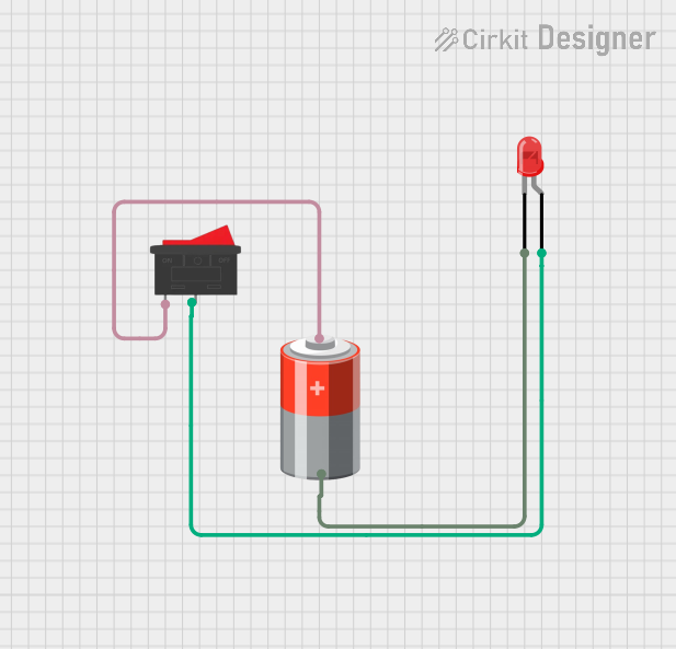
This document provides a detailed overview of a simple circuit consisting of a 5V battery, a rocker switch, and a red LED. The circuit is designed to control the LED using the rocker switch. When the switch is closed, the LED will light up, indicating the flow of current from the battery through the LED.
Component List
LED: Two Pin (red)
- Description: A red LED (Light Emitting Diode) with two pins: anode and cathode.
- Pins:
- Anode: Positive terminal
- Cathode: Negative terminal
Rocker Switch
- Description: A simple on/off switch with two pins.
- Pins:
- 1: First terminal
- 2: Second terminal
5V Battery
- Description: A 5V power source with two terminals.
- Pins:
- + (Positive): Positive terminal
- - (Negative): Negative terminal
Wiring Details
LED: Two Pin (red)
- Anode: Connected to pin 2 of the Rocker Switch.
- Cathode: Connected to the negative terminal (-) of the 5V Battery.
Rocker Switch
- Pin 1: Connected to the positive terminal (+) of the 5V Battery.
- Pin 2: Connected to the anode of the LED.
5V Battery
- Positive (+): Connected to pin 1 of the Rocker Switch.
- Negative (-): Connected to the cathode of the LED.
Code
There is no microcontroller code associated with this circuit.
This documentation provides a comprehensive overview of the circuit, including a summary, detailed component descriptions, and wiring details. The circuit is straightforward and does not include any microcontroller code.