
Battery-Powered Raspberry Pi Pico GPS Tracker with Sensor Integration
View and Edit Project In Cirkit Designer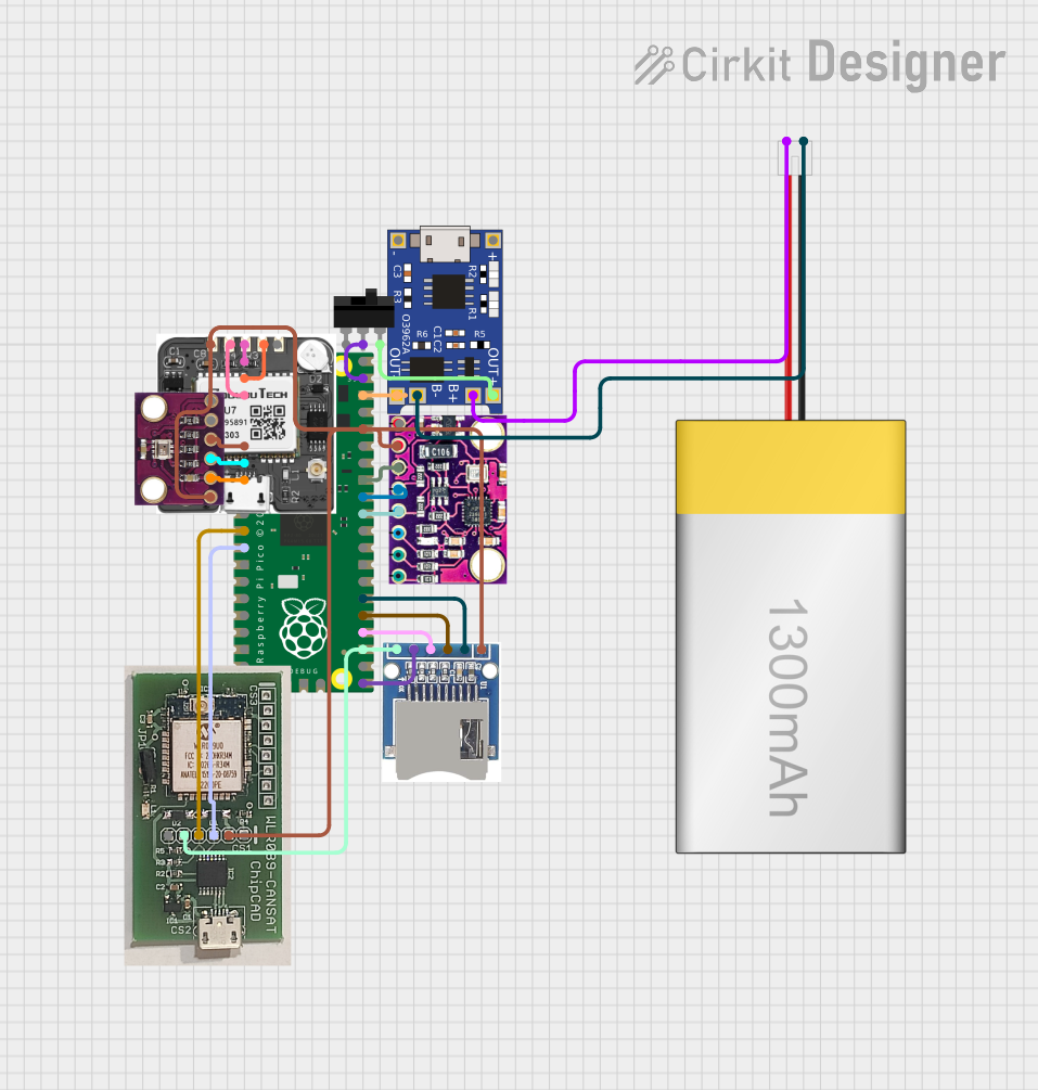
Circuit Documentation
Summary
This document provides a detailed overview of a circuit that includes a Raspberry Pi Pico microcontroller, various sensors, a GPS module, a battery management system, and other components. The circuit is designed to interface with multiple peripherals and manage power efficiently.
Component List
Raspberry Pi Pico
- Description: A microcontroller board based on the RP2040 microcontroller chip.
- Pins: pin 1 to pin 43
TP4056
- Description: A lithium battery charger module.
- Pins: OUT-, B-, B+, OUT+, IN-, IN+
LiPoly Battery (1300mAh)
- Description: A rechargeable lithium polymer battery.
- Pins: positive, negative
Toggle Switch
- Description: A simple on/off switch.
- Pins: L1, COM, L2
MPU9250/GY-91
- Description: A 9-axis motion tracking device.
- Pins: 3V3, GND, SCL, SDA, VIN/5V
neo 6m gps
- Description: A GPS module for location tracking.
- Pins: VCC, GND, RXD, TXD, PPS
BMP280
- Description: A barometric pressure sensor.
- Pins: VCC, GND, SCL, SDA, CSB, SDO
WLR089-CanSAT
- Description: A wireless communication module.
- Pins: USR, 3v6, TXD, RXD, GND, RES
SD SDHC
- Description: An SD card module for data storage.
- Pins: 3V3, CS, MOSI, CLK, MISO, GND
Wiring Details
Raspberry Pi Pico
- pin 1: Connected to neo 6m gps RXD
- pin 2: Connected to neo 6m gps TXD
- pin 3: Connected to neo 6m gps GND
- pin 6: Connected to BMP280 SDA
- pin 7: Connected to BMP280 SCL
- pin 8: Connected to BMP280 GND
- pin 11: Connected to WLR089-CanSAT RXD
- pin 12: Connected to WLR089-CanSAT TXD
- pin 21: Connected to SD SDHC MISO
- pin 23: Connected to WLR089-CanSAT GND, SD SDHC GND
- pin 24: Connected to SD SDHC CLK
- pin 25: Connected to SD SDHC MOSI
- pin 26: Connected to SD SDHC CS
- pin 31: Connected to MPU9250/GY-91 SDA
- pin 32: Connected to MPU9250/GY-91 SCL
- pin 33: Connected to MPU9250/GY-91 GND
- pin 36: Connected to WLR089-CanSAT 3v6, MPU9250/GY-91 3V3, SD SDHC 3V3, neo 6m gps VCC, BMP280 VCC
- pin 38: Connected to TP4056 OUT-
- pin 39: Connected to Toggle Switch COM
TP4056
- OUT-: Connected to Raspberry Pi Pico pin 38
- B-: Connected to LiPoly Battery (1300mAh) negative
- B+: Connected to LiPoly Battery (1300mAh) positive
- OUT+: Connected to Toggle Switch L2
LiPoly Battery (1300mAh)
- positive: Connected to TP4056 B+
- negative: Connected to TP4056 B-
Toggle Switch
- L1: Not connected
- COM: Connected to Raspberry Pi Pico pin 39
- L2: Connected to TP4056 OUT+
MPU9250/GY-91
- 3V3: Connected to Raspberry Pi Pico pin 36
- GND: Connected to Raspberry Pi Pico pin 33
- SCL: Connected to Raspberry Pi Pico pin 32
- SDA: Connected to Raspberry Pi Pico pin 31
- VIN/5V: Not connected
neo 6m gps
- VCC: Connected to Raspberry Pi Pico pin 36
- GND: Connected to Raspberry Pi Pico pin 3
- RXD: Connected to Raspberry Pi Pico pin 1
- TXD: Connected to Raspberry Pi Pico pin 2
- PPS: Not connected
BMP280
- VCC: Connected to Raspberry Pi Pico pin 36
- GND: Connected to Raspberry Pi Pico pin 8
- SCL: Connected to Raspberry Pi Pico pin 7
- SDA: Connected to Raspberry Pi Pico pin 6
- CSB: Not connected
- SDO: Not connected
WLR089-CanSAT
- 3v6: Connected to Raspberry Pi Pico pin 36
- GND: Connected to Raspberry Pi Pico pin 23
- RXD: Connected to Raspberry Pi Pico pin 11
- TXD: Connected to Raspberry Pi Pico pin 12
- USR: Not connected
- RES: Not connected
SD SDHC
- 3V3: Connected to Raspberry Pi Pico pin 36
- GND: Connected to Raspberry Pi Pico pin 23
- CS: Connected to Raspberry Pi Pico pin 26
- MOSI: Connected to Raspberry Pi Pico pin 25
- CLK: Connected to Raspberry Pi Pico pin 24
- MISO: Connected to Raspberry Pi Pico pin 21
Documented Code
Raspberry Pi Pico Code
void setup() {
  // put your setup code here, to run once:

}

void loop() {
  // put your main code here, to run repeatedly:

}
This concludes the documentation for the circuit. Each component is connected as specified, and the provided code is a basic template for the Raspberry Pi Pico.