Cirkit Designer
Your all-in-one circuit design IDE
Home /
Project Documentation
Arduino UNO-Based Smart Alarm System with Ultrasonic, Gas, and Light Sensors
Circuit Documentation
Summary
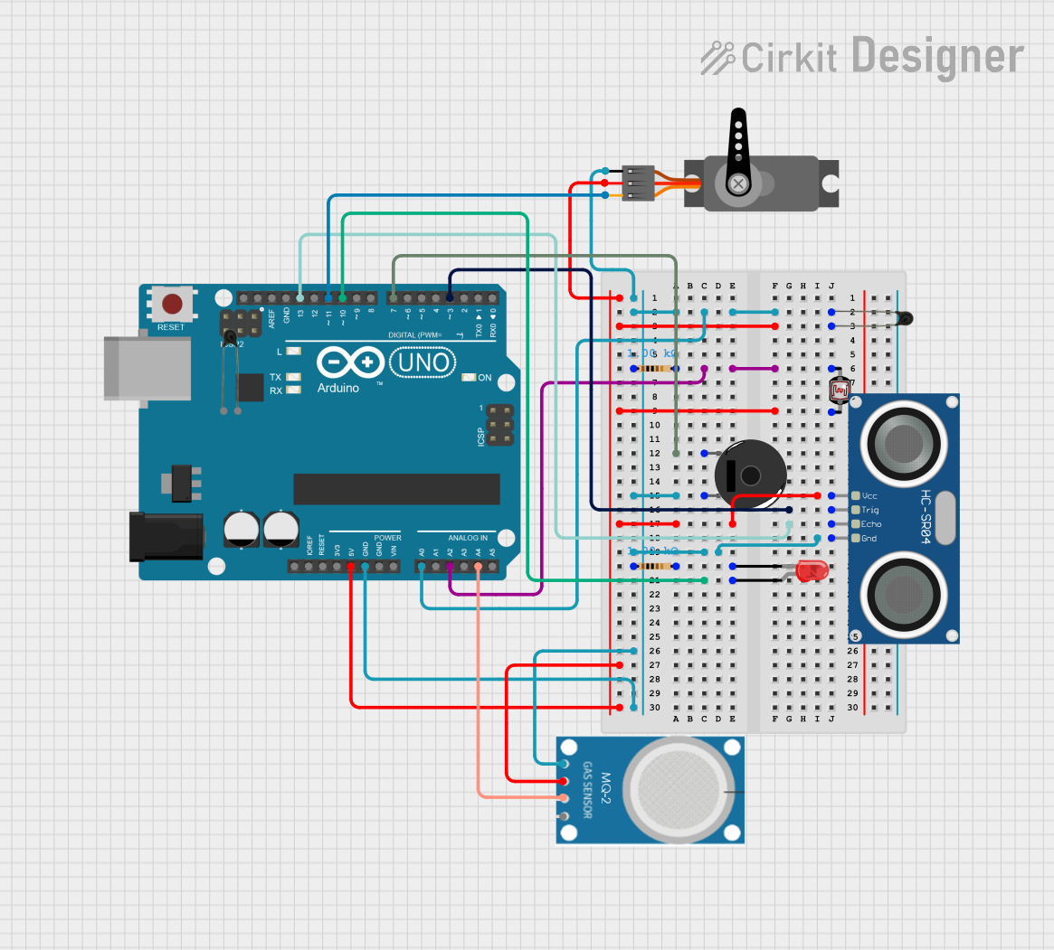
This circuit is designed to monitor environmental conditions using various sensors and respond accordingly. It includes an Arduino UNO microcontroller, temperature sensor (NTC), light-dependent resistor (LDR), gas sensor (MQ-2), ultrasonic sensor (HC-SR04), servo motor, piezo buzzer, and an LED. The system reads sensor values and triggers an alarm or controls the servo motor based on predefined thresholds.
Component List
Arduino UNO
- Description: Microcontroller board based on the ATmega328P.
- Pins: UNUSED, IOREF, Reset, 3.3V, 5V, GND, Vin, A0, A1, A2, A3, A4, A5, SCL, SDA, AREF, D13, D12, D11, D10, D9, D8, D7, D6, D5, D4, D3, D2, D1, D0
NTC (Temperature Sensor)
- Description: Negative Temperature Coefficient thermistor used for temperature measurement.
- Pins: A0, A1
Photocell (LDR)
- Description: Light-dependent resistor used to measure light intensity.
- Pins: pin 0, pin 1
Servo
- Description: Servo motor used for precise control of angular position.
- Pins: GND, VCC, PWM
LED: Two Pin (red)
- Description: Red LED used for visual indication.
- Pins: cathode, anode
Piezo Buzzer
- Description: Buzzer used for sound indication.
- Pins: pin 1, pin 2
Resistor
- Description: Resistor used to limit current.
- Pins: pin1, pin2
- Properties: Resistance: 1000 Ohms
HC-SR04 Ultrasonic Sensor
- Description: Ultrasonic sensor used for distance measurement.
- Pins: VCC, TRIG, ECHO, GND
MQ-2
- Description: Gas sensor used to detect gas levels.
- Pins: GND, VCC, ANALOG, Digital
Wiring Details
Arduino UNO
- A0: Connected to NTC (A0), Resistor (pin1), Piezo Buzzer (pin 2)
- A2: Connected to Photocell (LDR) (pin 0), Resistor (pin2)
- A4: Connected to MQ-2 (ANALOG)
- D3: Connected to HC-SR04 Ultrasonic Sensor (TRIG)
- D7: Connected to Piezo Buzzer (pin 1)
- D10: Connected to LED (anode)
- D11: Connected to Servo (PWM)
- D13: Connected to HC-SR04 Ultrasonic Sensor (ECHO)
- 5V: Connected to HC-SR04 Ultrasonic Sensor (VCC), Servo (VCC), MQ-2 (VCC)
- GND: Connected to NTC (A0), Resistor (pin1), Piezo Buzzer (pin 2), HC-SR04 Ultrasonic Sensor (GND), Servo (GND), MQ-2 (GND)
NTC (Temperature Sensor)
- A0: Connected to Arduino UNO (A0), Resistor (pin1), Piezo Buzzer (pin 2)
- A1: Connected to Photocell (LDR) (pin 1), HC-SR04 Ultrasonic Sensor (VCC), Servo (VCC), MQ-2 (VCC), Arduino UNO (5V)
Photocell (LDR)
- pin 0: Connected to Resistor (pin2), Arduino UNO (A2)
- pin 1: Connected to NTC (A1), HC-SR04 Ultrasonic Sensor (VCC), Servo (VCC), MQ-2 (VCC), Arduino UNO (5V)
Servo
- GND: Connected to Arduino UNO (GND)
- VCC: Connected to NTC (A1), Photocell (LDR) (pin 1), HC-SR04 Ultrasonic Sensor (VCC), MQ-2 (VCC), Arduino UNO (5V)
- PWM: Connected to Arduino UNO (D11)
LED: Two Pin (red)
- cathode: Connected to Resistor (pin2)
- anode: Connected to Arduino UNO (D10)
Piezo Buzzer
- pin 1: Connected to Arduino UNO (D7)
- pin 2: Connected to NTC (A0), Resistor (pin1), Arduino UNO (A0)
Resistor
- pin1: Connected to NTC (A0), Piezo Buzzer (pin 2), Arduino UNO (A0)
- pin2: Connected to Photocell (LDR) (pin 0), LED (cathode), Arduino UNO (A2)
HC-SR04 Ultrasonic Sensor
- VCC: Connected to NTC (A1), Photocell (LDR) (pin 1), Servo (VCC), MQ-2 (VCC), Arduino UNO (5V)
- TRIG: Connected to Arduino UNO (D3)
- ECHO: Connected to Arduino UNO (D13)
- GND: Connected to NTC (A0), Resistor (pin1), Piezo Buzzer (pin 2), Servo (GND), MQ-2 (GND), Arduino UNO (GND)
MQ-2
- GND: Connected to NTC (A0), Resistor (pin1), Piezo Buzzer (pin 2), HC-SR04 Ultrasonic Sensor (GND), Servo (GND), Arduino UNO (GND)
- VCC: Connected to NTC (A1), Photocell (LDR) (pin 1), HC-SR04 Ultrasonic Sensor (VCC), Servo (VCC), Arduino UNO (5V)
- ANALOG: Connected to Arduino UNO (A4)
- Digital: Not connected
Code Documentation
#include <Servo.h>

// Pin Definitions
#define LDRpin A2        // LDR Sensor Pin
#define MQ2pin A4        // MQ-2 Gas Sensor Pin
#define TEMPpin A0       // Temperature Sensor (KY-028) Pin
const int TRIG_PIN = 3;  // Ultrasonic Sensor TRIG pin
const int ECHO_PIN = 13; // Ultrasonic Sensor ECHO pin
const int SERVO_PIN = 11; // Servo Motor pin
const int BUZZER_PIN = 7; // Buzzer pin
const int LED_PIN = 10;  // LED pin

// Thresholds
const int DISTANCE_THRESHOLD = 10; // Ultrasonic Distance Threshold in cm
const int TEMP_THRESHOLD = 50;    // Temperature Threshold (raw value)
const int GAS_THRESHOLD = 200;    // Gas Threshold (raw value)
const int LDR_THRESHOLD = 100;    // LDR Threshold (raw value)

// Global Variables
Servo servo;          // Servo Motor Object
float distance_cm;    // Ultrasonic Sensor Value
float tempValue;      // Temperature Sensor Value
float gasValue;       // MQ-2 Gas Sensor Value
int LDRValue;         // LDR Sensor Value

void setup() {
  Serial.begin(9600); // Initialize Serial Monitor

  // Pin Modes
  pinMode(TRIG_PIN, OUTPUT);
  pinMode(ECHO_PIN, INPUT);
  pinMode(BUZZER_PIN, OUTPUT);
  pinMode(LED_PIN, OUTPUT);
  pinMode(LDRpin, INPUT);
  pinMode(MQ2pin, INPUT);
  pinMode(TEMPpin, INPUT);

  servo.attach(SERVO_PIN);
  servo.write(90); // Initial state: Servo closed

  // Ensure initial states
  digitalWrite(BUZZER_PIN, LOW);
  digitalWrite(LED_PIN, LOW);
}

void updateUltrasonic() {
  digitalWrite(TRIG_PIN, LOW);
  delayMicroseconds(2);
  digitalWrite(TRIG_PIN, HIGH);
  delayMicroseconds(10);
  digitalWrite(TRIG_PIN, LOW);
  float duration_us = pulseIn(ECHO_PIN, HIGH);
  distance_cm = 0.017 * duration_us;
  if (distance_cm <= 0 || distance_cm > 400) {
    distance_cm = 400; // Out of range
  }
}

void updateSensorValues() {
  tempValue = analogRead(TEMPpin);
  gasValue = analogRead(MQ2pin);
}

bool isAlarmConditionActive() {
  return (tempValue < TEMP_THRESHOLD || gasValue > GAS_THRESHOLD);
}

void playAlarm() {
  while (true) {
    digitalWrite(LED_PIN, HIGH); // Turn on the LED
    Serial.println("Alarm is active!");

    // Check sensor values before each pattern
    updateSensorValues();
    if (!isAlarmConditionActive()) {
      Serial.println("Conditions returned to normal - stopping alarm");
      stopAlarm();
      break;
    }

    // Pattern 1
    for (int i = 0; i < 80; i++) {
      digitalWrite(BUZZER_PIN, HIGH);
      delay(1);
      digitalWrite(BUZZER