Arduino and Raspberry Pi Multi-Sensor Monitoring System with GPS and LCD Display
Circuit Documentation
Summary
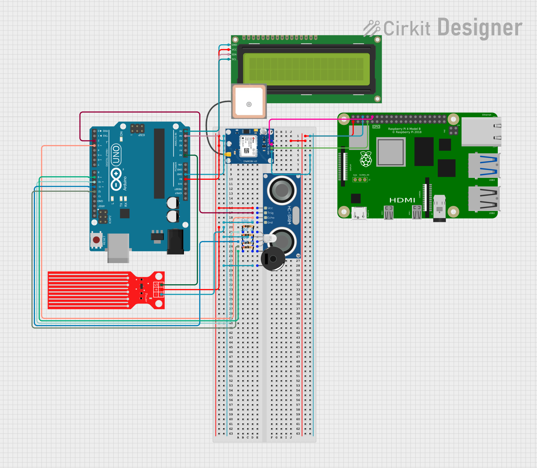
This circuit integrates a variety of components including an Arduino UNO, an HC-SR04 Ultrasonic Sensor, a 16x2 I2C LCD, a Raspberry Pi 4B, a Piezo Buzzer, a Water Level Sensor, an RGB LED, a GPS NEO 6M module, and several resistors. The Arduino UNO serves as the primary microcontroller, interfacing with sensors, an LCD display, and an RGB LED. The Raspberry Pi 4B is used in conjunction with the GPS module, likely for more complex processing and positioning capabilities. The circuit is powered by the 5V output from the Arduino UNO and the 3.3V output from the Raspberry Pi for different components.
Component List
Arduino UNO
- Microcontroller board based on the ATmega328P
- Provides digital I/O pins, analog inputs, and various power outputs
HC-SR04 Ultrasonic Sensor
- Measures distance by emitting ultrasonic waves and measuring the time taken for the echo to return
16x2 I2C LCD
- Alphanumeric liquid crystal display with an I2C interface for displaying text
Raspberry Pi 4B
- A powerful single-board computer with GPIO pins for interfacing with various peripherals
Piezo Buzzer
- An electronic device that emits sound when an electric signal is applied
Water Level Sensor
- Detects the level of water in a container or environment
RGB LED (Wokwi compatible)
- A light-emitting diode that can display multiple colors through the combination of red, green, and blue
GPS NEO 6M
- A GPS module capable of providing geographical positioning information
Resistor (200 Ohms)
- A passive two-terminal electrical component that implements electrical resistance
Wiring Details
Arduino UNO
- 5V: Powers the 16x2 I2C LCD, HC-SR04 Ultrasonic Sensor, and Water Level Sensor
- GND: Common ground for the 16x2 I2C LCD, HC-SR04 Ultrasonic Sensor, Water Level Sensor, RGB LED, and Piezo Buzzer
- D2: Connected to the TRIG pin of the HC-SR04 Ultrasonic Sensor
- D3: Connected to the ECHO pin of the HC-SR04 Ultrasonic Sensor
- D9: Connected to the Piezo Buzzer through a 200 Ohm resistor
- D10, D11, D12: Connected to the R, G, B pins of the RGB LED through 200 Ohm resistors respectively
- A0: Connected to the SIG pin of the Water Level Sensor
- A4 (SDA), A5 (SCL): Connected to the SDA and SCL pins of the 16x2 I2C LCD
HC-SR04 Ultrasonic Sensor
- VCC: Powered by the Arduino UNO's 5V
- GND: Common ground with Arduino UNO
- TRIG: Connected to D2 on the Arduino UNO
- ECHO: Connected to D3 on the Arduino UNO
16x2 I2C LCD
- VCC: Powered by the Arduino UNO's 5V
- GND: Common ground with Arduino UNO
- SDA: Connected to A4 on the Arduino UNO
- SCL: Connected to A5 on the Arduino UNO
Raspberry Pi 4B
- 3V3: Powers the GPS NEO 6M module
- GND: Common ground with GPS NEO 6M module
- GPIO4: Connected to the TX pin of the GPS NEO 6M module
- GPIO15: Connected to the RX pin of the GPS NEO 6M module
Piezo Buzzer
- Pin 1: Connected to D9 on the Arduino UNO through a 200 Ohm resistor
- Pin 2: Common ground with Arduino UNO
Water Level Sensor
- VCC: Powered by the Arduino UNO's 5V
- GND: Common ground with Arduino UNO
- SIG: Connected to A0 on the Arduino UNO
RGB LED (Wokwi compatible)
- R: Connected to D10 on the Arduino UNO through a 200 Ohm resistor
- G: Connected to D11 on the Arduino UNO through a 200 Ohm resistor
- B: Connected to D12 on the Arduino UNO through a 200 Ohm resistor
- COM: Common ground with Arduino UNO
GPS NEO 6M
- VCC: Powered by the Raspberry Pi 4B's 3V3
- GND: Common ground with Raspberry Pi 4B
- RX: Connected to GPIO15 on the Raspberry Pi 4B
- TX: Connected to GPIO4 on the Raspberry Pi 4B
Resistor (200 Ohms)
- Used in series with the RGB LED and Piezo Buzzer to limit current
Documented Code
Arduino UNO Code (sketch.ino)
void setup() {
  // put your setup code here, to run once:

}

void loop() {
  // put your main code here, to run repeatedly:

}
Note: The provided code for the Arduino UNO is a template with empty setup and loop functions. The actual functionality needs to be implemented based on the specific requirements of the circuit.