
ESP32-Based Smart Environmental Monitoring System with Wi-Fi Control
View and Edit Project In Cirkit Designer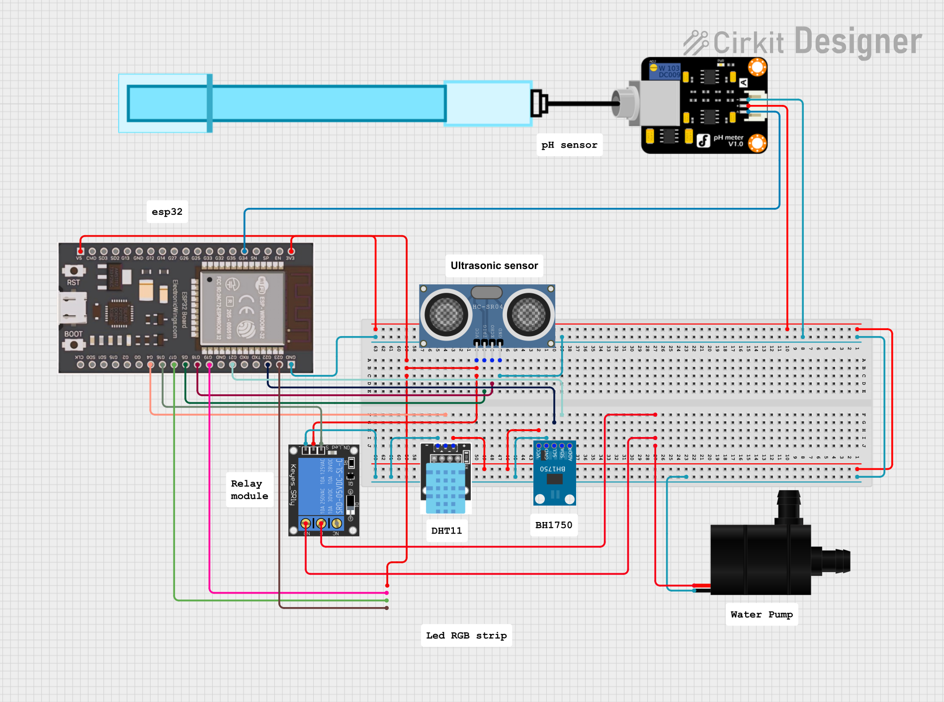
Circuit Documentation
Summary
This circuit is designed to monitor environmental conditions using various sensors and control a water pump and an RGB LED strip based on the sensor readings. The main components include an ESP32 microcontroller, a DHT11 temperature-humidity sensor, an HC-SR04 ultrasonic distance sensor, a BH1750 light sensor, a pH meter, a 1-channel relay, a water pump, and an RGB LED strip.
Component List
ESP32
- Description: A powerful microcontroller with Wi-Fi and Bluetooth capabilities.
- Pins: V5, CMD, SD3, SD2, G13, GND, G12, G14, G27, G26, G25, G33, G32, G35, G34, SN, SP, EN, 3V3, G23, G22, TXD, RXD, G21, G19, G18, G5, G17, G16, G4, G0, G2, G15, SD1, SD0, CLK
KY-015 DHT11 Temperature-Humidity Sensor Module
- Description: A sensor module for measuring temperature and humidity.
- Pins: VCC, GND, DOUT
HC-SR04 Ultrasonic Distance Sensor
- Description: A sensor module for measuring distance using ultrasonic waves.
- Pins: VCC, TRIG, ECHO, GND
BH1750
- Description: A light intensity sensor.
- Pins: VCC, GND, SCL, SDA, ADDR
PH Meter
- Description: A sensor module for measuring pH levels.
- Pins: Signal, VCC, GND
1-Channel Relay (5V 10A)
- Description: A relay module for controlling high-power devices.
- Pins: NC, signal, C, power, NO, ground
Water Pump
- Description: A pump for moving water.
- Pins: VCC, GND
LED RGB Strip
- Description: An RGB LED strip for lighting.
- Pins: Common Connect, Blue Connect, Red Connect, Green Connect
Wiring Details
ESP32
- 3V3: Connected to VCC of PH Meter, BH1750, and KY-015 DHT11 Temperature-Humidity Sensor Module.
- GND: Connected to GND of PH Meter, Water Pump, HC-SR04 Ultrasonic Distance Sensor, BH1750, KY-015 DHT11 Temperature-Humidity Sensor Module, and 1-Channel Relay.
- V5: Connected to VCC of HC-SR04 Ultrasonic Distance Sensor, Common Connect of LED RGB Strip, and power of 1-Channel Relay.
- G21: Connected to SDA of BH1750.
- G22: Connected to SCL of BH1750.
- G18: Connected to ECHO of HC-SR04 Ultrasonic Distance Sensor.
- G5: Connected to TRIG of HC-SR04 Ultrasonic Distance Sensor.
- G4: Connected to DOUT of KY-015 DHT11 Temperature-Humidity Sensor Module.
- G34: Connected to Signal of PH Meter.
- G23: Connected to Blue Connect of LED RGB Strip.
- G19: Connected to Green Connect of LED RGB Strip.
- G17: Connected to Red Connect of LED RGB Strip.
- G16: Connected to signal of 1-Channel Relay.
KY-015 DHT11 Temperature-Humidity Sensor Module
- VCC: Connected to 3V3 of ESP32.
- GND: Connected to GND of ESP32.
- DOUT: Connected to G4 of ESP32.
HC-SR04 Ultrasonic Distance Sensor
- VCC: Connected to V5 of ESP32.
- GND: Connected to GND of ESP32.
- TRIG: Connected to G5 of ESP32.
- ECHO: Connected to G18 of ESP32.
BH1750
- VCC: Connected to 3V3 of ESP32.
- GND: Connected to GND of ESP32.
- SCL: Connected to G22 of ESP32.
- SDA: Connected to G21 of ESP32.
PH Meter
- VCC: Connected to 3V3 of ESP32.
- GND: Connected to GND of ESP32.
- Signal: Connected to G34 of ESP32.
1-Channel Relay (5V 10A)
- power: Connected to V5 of ESP32.
- ground: Connected to GND of ESP32.
- signal: Connected to G16 of ESP32.
- C: Connected to NO of 1-Channel Relay.
- NO: Connected to VCC of Water Pump.
Water Pump
- VCC: Connected to NO of 1-Channel Relay.
- GND: Connected to GND of ESP32.
LED RGB Strip
- Common Connect: Connected to V5 of ESP32.
- Blue Connect: Connected to G23 of ESP32.
- Green Connect: Connected to G19 of ESP32.
- Red Connect: Connected to G17 of ESP32.
Code Documentation
#include <Wire.h>
#include <Adafruit_Sensor.h>
#include <DHT.h>
#include <BH1750.h>

// Pin Definitions
#define DHTPIN 4
#define DHTTYPE DHT11
#define TRIG_PIN 5
#define ECHO_PIN 18
#define RELAY_PIN 16
#define RED_PIN 17
#define GREEN_PIN 19
#define BLUE_PIN 23

// Sensor Objects
DHT dht(DHTPIN, DHTTYPE);
BH1750 lightMeter;

void setup() {
  // Initialize Serial Monitor
  Serial.begin(115200);

  // Initialize DHT11 Sensor
  dht.begin();

  // Initialize BH1750 Sensor
  Wire.begin();
  lightMeter.begin();

  // Initialize Ultrasonic Sensor
  pinMode(TRIG_PIN, OUTPUT);
  pinMode(ECHO_PIN, INPUT);

  // Initialize Relay
  pinMode(RELAY_PIN, OUTPUT);
  digitalWrite(RELAY_PIN, LOW); // Turn off relay initially

  // Initialize RGB LED Strip
  pinMode(RED_PIN, OUTPUT);
  pinMode(GREEN_PIN, OUTPUT);
  pinMode(BLUE_PIN, OUTPUT);
}

void loop() {
  // Read DHT11 Sensor
  float humidity = dht.readHumidity();
  float temperature = dht.readTemperature();
  Serial.print("Humidity: ");
  Serial.print(humidity);
  Serial.print("%, Temperature: ");
  Serial.print(temperature);
  Serial.println("°C");

  // Read BH1750 Sensor
  float lux = lightMeter.readLightLevel();
  Serial.print("Light: ");
  Serial.print(lux);
  Serial.println(" lx");

  // Read Ultrasonic Sensor
  long duration, distance;
  digitalWrite(TRIG_PIN, LOW);
  delayMicroseconds(2);
  digitalWrite(TRIG_PIN, HIGH);
  delayMicroseconds(10);
  digitalWrite(TRIG_PIN, LOW);
  duration = pulseIn(ECHO_PIN, HIGH);
  distance = (duration / 2) / 29.1;
  Serial.print("Distance: ");
  Serial.print(distance);
  Serial.println(" cm");

  // Control Relay and Water Pump
  if (distance < 10) { // Example condition to turn on the pump
    digitalWrite(RELAY_PIN, HIGH);
  } else {
    digitalWrite(RELAY_PIN, LOW);
  }

  // Control RGB LED Strip
  if (lux < 50) { // Example condition to change color
    setColor(255, 0, 0); // Red
  } else if (lux < 100) {
    setColor(0, 255, 0); // Green
  } else {
    setColor(0, 0, 255); // Blue
  }

  delay(2000); // Wait for 2 seconds before next loop
}

void setColor(int red, int green, int blue) {
  analogWrite(RED_PIN, red);
  analogWrite(GREEN_PIN, green);
  analogWrite(BLUE_PIN, blue);
}
This code initializes and reads data from the DHT11, BH1750, and HC-SR04 sensors, and controls the relay and RGB LED strip based on the sensor readings. The relay is used to control the water pump, and the RGB LED strip changes color based on the light intensity measured by the BH1750 sensor.