
Circuit Documentation
Summary
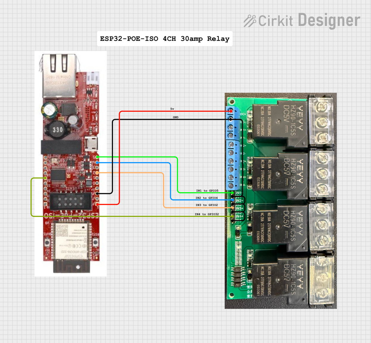
This document provides a detailed overview of a circuit that includes an ESP32-POE-ISO microcontroller and a 4 Channel 30A 5V Relay module. The ESP32 microcontroller is used to control the relay module, which can switch high-power devices. The circuit is designed to be powered by a 5V supply and includes several comments for documentation purposes.
Component List
ESP32-POE-ISO
- Description: A microcontroller with Power over Ethernet (PoE) capability.
- Pins: GPI39 (VN), GPI36 (VP), GPI35, GPI34, GPIO33, GPIO32, GPIO16, GPIO15, GPIO14, GPIO13, 5v, 3.3v, GND, EN, GPIO0, GPIO1, GPIO2, GPIO3, GPIO4, GPIO5
4 Channel 30A 5V Relay
- Description: A relay module capable of switching high-power devices, controlled by a 5V signal.
- Pins: 5V, GND, IN1+, IN1-, IN2+, IN2-, IN3+, IN3-, IN4+, IN4-
Comment
- Description: Placeholder for comments in the circuit.
- Pins: None
Wiring Details
ESP32-POE-ISO
- GPIO32 is connected to IN4+ of the 4 Channel 30A 5V Relay.
- 5v is connected to 5V of the 4 Channel 30A 5V Relay.
- GND is connected to GND, IN1-, IN2-, IN3-, and IN4- of the 4 Channel 30A 5V Relay.
- GPIO2 is connected to IN3+ of the 4 Channel 30A 5V Relay.
- GPIO4 is connected to IN2+ of the 4 Channel 30A 5V Relay.
- GPIO5 is connected to IN1+ of the 4 Channel 30A 5V Relay.
4 Channel 30A 5V Relay
- IN4+ is connected to GPIO32 of the ESP32-POE-ISO.
- 5V is connected to 5v of the ESP32-POE-ISO.
- GND is connected to GND of the ESP32-POE-ISO.
- IN1- is connected to GND of the ESP32-POE-ISO.
- IN2- is connected to GND of the ESP32-POE-ISO.
- IN3- is connected to GND of the ESP32-POE-ISO.
- IN4- is connected to GND of the ESP32-POE-ISO.
- IN3+ is connected to GPIO2 of the ESP32-POE-ISO.
- IN2+ is connected to GPIO4 of the ESP32-POE-ISO.
- IN1+ is connected to GPIO5 of the ESP32-POE-ISO.
Documented Code
No code is provided for this circuit.