Arduino Mega 2560-Based Rotary Encoder Control with Multiple Pushbuttons
Circuit Documentation
Summary
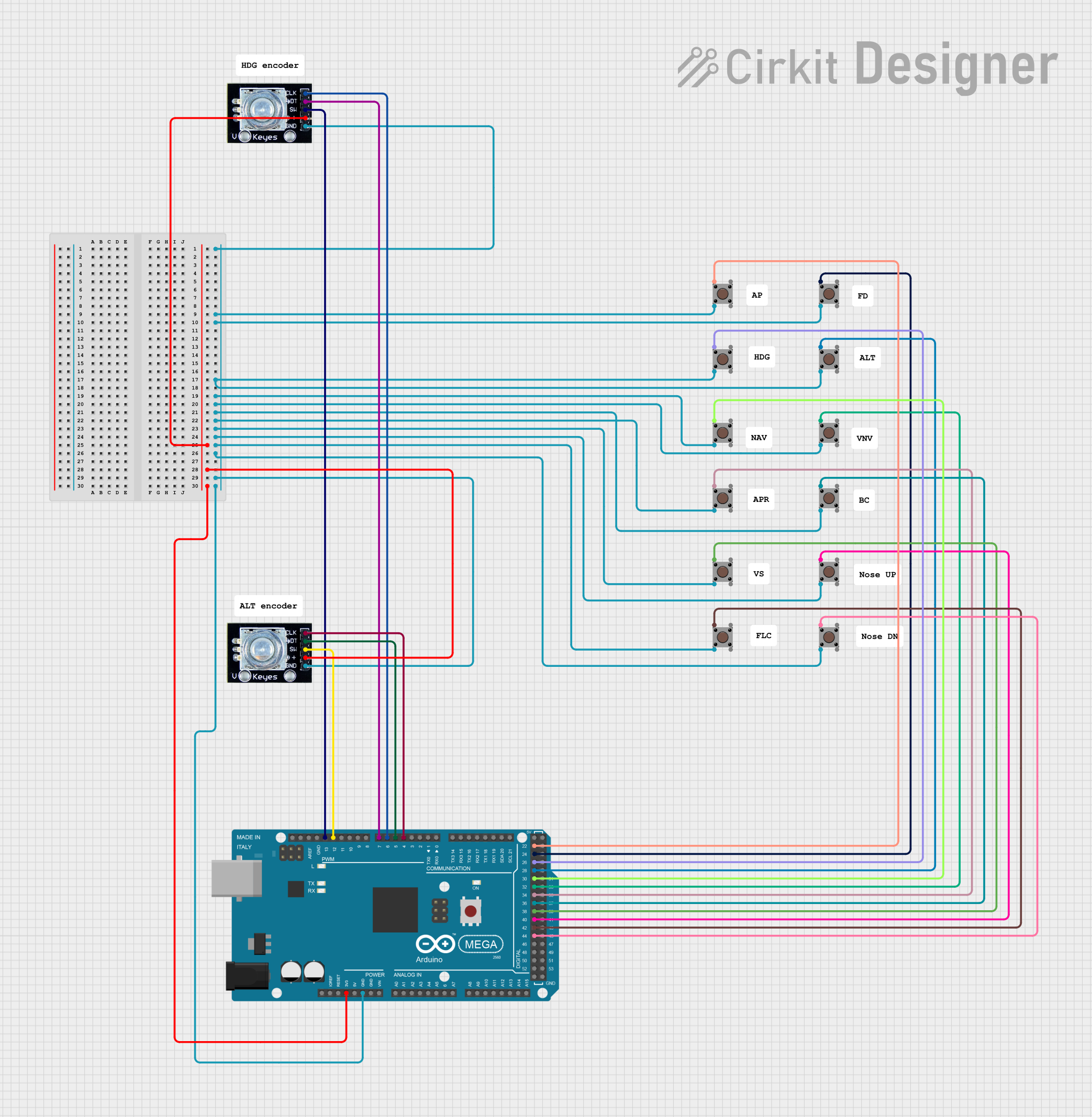
This circuit is designed using an Arduino Mega 2560 microcontroller, which interfaces with multiple pushbuttons and rotary encoders. The pushbuttons are used for user input, while the rotary encoders provide additional control options. The circuit is powered by a 3.3V supply and utilizes various digital pins for reading the states of the buttons and encoders.
Component List
1. Arduino Mega 2560
- Description: A microcontroller board based on the ATmega2560. It has 54 digital input/output pins, 16 analog inputs, a USB connection, a power jack, an ICSP header, and a reset button.
- Purpose: Acts as the main control unit for the circuit, processing inputs from the pushbuttons and rotary encoders.
2. Pushbutton
- Description: A simple switch that closes the circuit when pressed.
- Purpose: Used for user input to trigger actions in the circuit.
3. Rotary Encoder
- Description: A device that converts the angular position or motion of a shaft or axle to an analog or digital signal.
- Purpose: Provides a way to control parameters in the circuit, such as volume or speed, by rotating the encoder.
Wiring Details
Arduino Mega 2560
GND: Connected to the ground of the rotary encoders and pushbuttons.
3V3: Connected to the power pins of the rotary encoders.
D4 PWM: Connected to the
clkpin of the rotary encoder.D5 PWM: Connected to the
dtpin of the rotary encoder.D6 PWM: Connected to the
clkpin of another rotary encoder.D7 PWM: Connected to the
dtpin of another rotary encoder.D12 PWM: Connected to the
swpin of the second rotary encoder.D13 PWM: Connected to the
swpin of the first rotary encoder.D44: Connected to
Pin 1 (in)of a pushbutton.D42: Connected to
Pin 1 (in)of another pushbutton.D40: Connected to
Pin 1 (in)of another pushbutton.D38: Connected to
Pin 1 (in)of another pushbutton.D36: Connected to
Pin 1 (in)of another pushbutton.D34: Connected to
Pin 1 (in)of another pushbutton.D32: Connected to
Pin 1 (in)of another pushbutton.D30: Connected to
Pin 1 (in)of another pushbutton.D28: Connected to
Pin 1 (in)of another pushbutton.D26: Connected to
Pin 1 (in)of another pushbutton.D24: Connected to
Pin 1 (in)of another pushbutton.D22: Connected to
Pin 1 (in)of another pushbutton.
Documented Code
void setup() {
  // put your setup code here, to run once:

}

void loop() {
  // put your main code here, to run repeatedly:

}
This documentation provides a comprehensive overview of the circuit, detailing the components used, their wiring, and the code that runs on the Arduino Mega 2560.