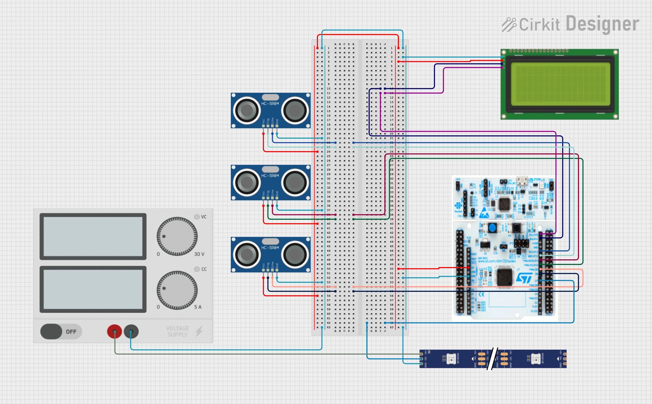
STM32 Nucleo F303RE Controlled Ultrasonic Sensing with RGB Feedback and I2C LCD Display

Circuit Documentation
Summary
This circuit integrates multiple components to perform a variety of functions. It includes three HC-SR04 Ultrasonic Sensors for distance measurement, an LCD 20x4 I2C module for data display, an STM32 Nucleo F303RE microcontroller as the central processing unit, a WS2812 RGB LED strip for visual feedback, and a Power Supply to provide the necessary voltage and current to the system.
Component List
HC-SR04 Ultrasonic Sensor
- Description: An ultrasonic distance sensor that uses sonar to determine the distance to an object.
- Pins: VCC, TRIG, ECHO, GND
Lcd 20x4 i2c
- Description: A 20x4 character LCD display with an I2C interface for displaying data.
- Pins: GND, 5v, SCA, SCL
STM32 Nucleo F303RE
- Description: A microcontroller board based on the STM32F303RE MCU, which is suitable for a wide range of applications.
- Pins: Multiple GPIOs, power, and ground pins.
WS2812 RGB LED strip
- Description: An addressable LED strip that can display multiple colors.
- Pins: DIN, 5V, GND, DO
Power Supply
- Description: Provides regulated voltage and current to power the circuit.
- Pins: + (positive supply), - (ground)
Wiring Details
HC-SR04 Ultrasonic Sensor
- VCC: Connected to +5V from the STM32 Nucleo F303RE.
- TRIG: Connected to digital pins D12, D10, and D8 on the STM32 Nucleo F303RE for each sensor respectively.
- ECHO: Connected to digital pins D13, D11, and D9 on the STM32 Nucleo F303RE for each sensor respectively.
- GND: Connected to the ground plane.
Lcd 20x4 i2c
- GND: Connected to the ground plane.
- 5v: Connected to +5V from the STM32 Nucleo F303RE.
- SCA: Connected to pin D14 on the STM32 Nucleo F303RE.
- SCL: Connected to pin D15 on the STM32 Nucleo F303RE.
STM32 Nucleo F303RE
- +5V: Provides power to the LCD and Ultrasonic Sensors.
- GND: Common ground for all components.
- D14 (SCA): I2C SCA line for the LCD.
- D15 (SCL): I2C SCL line for the LCD.
- D13, D11, D9: Connected to ECHO pins of the Ultrasonic Sensors.
- D12, D10, D8: Connected to TRIG pins of the Ultrasonic Sensors.
- D7: Connected to the DO pin of the WS2812 RGB LED strip.
WS2812 RGB LED strip
- DIN: Not connected in this circuit.
- 5V: Connected to the + terminal of the Power Supply.
- GND: Connected to the ground plane.
- DO: Connected to pin D7 on the STM32 Nucleo F303RE.
Power Supply
- +: Provides +5V to the WS2812 RGB LED strip.
- -: Connected to the ground plane.
Documented Code
There is no code provided for the microcontroller. The code would typically initialize and configure the microcontroller's peripherals, such as GPIOs for the HC-SR04 sensors, I2C for the LCD, and PWM or digital output for the WS2812 RGB LED strip. It would also contain the main application logic to read sensor data, process it, and output results to the LCD and LED strip.