Cirkit Designer
Your all-in-one circuit design IDE
Home /
Project Documentation
Arduino and ESP32-CAM Based Temperature Monitoring and Timekeeping System
Circuit Documentation
Summary
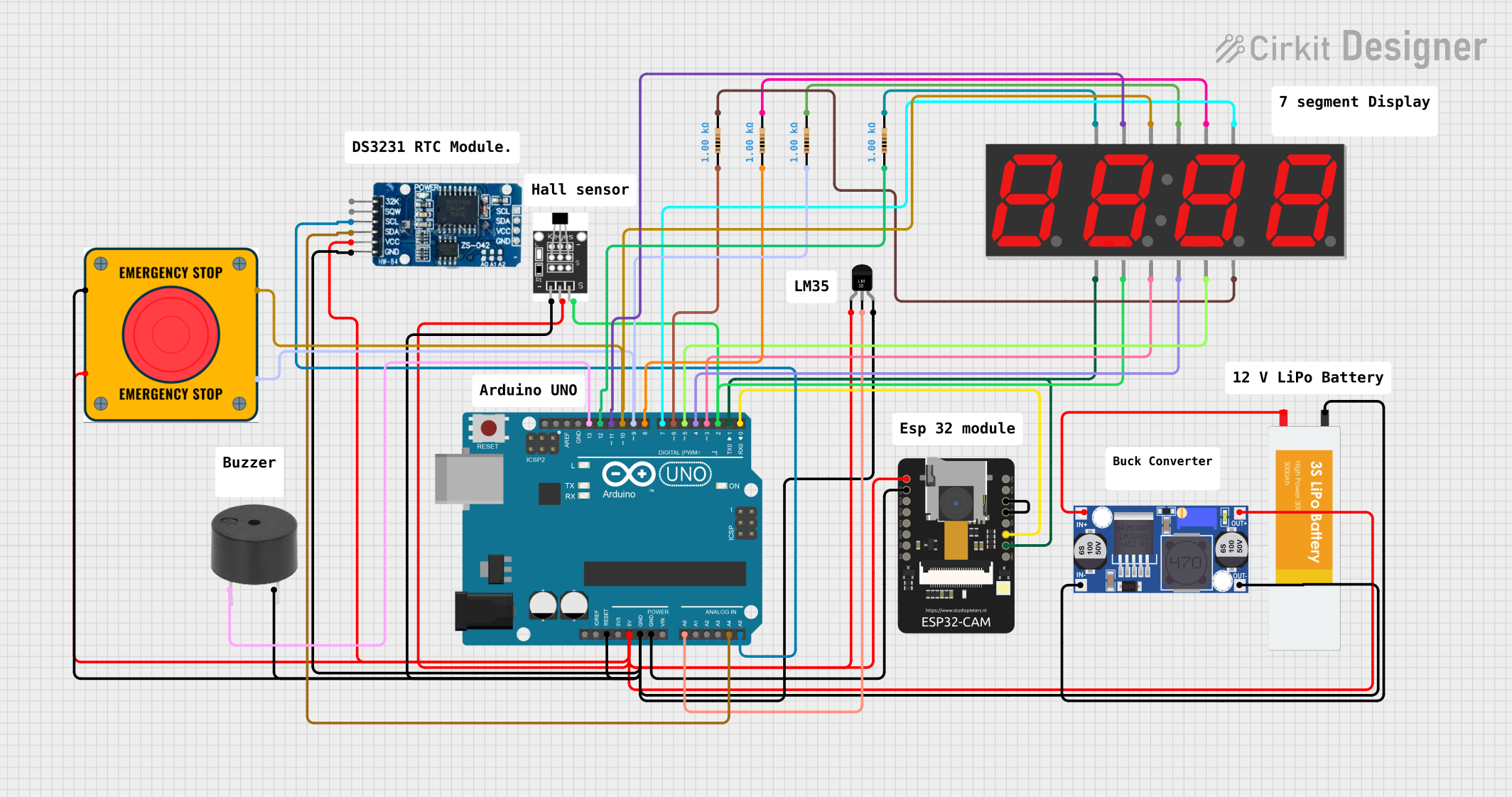
This document provides a detailed overview of a circuit designed to interface various sensors, a real-time clock (RTC), a display, and microcontrollers. The circuit is powered by a Lipo battery, regulated by a buck converter, and controlled by an Arduino UNO and an ESP32-CAM module. It includes a temperature sensor (LM35), a real-time clock (RTC DS3231), a 4-digit 7-segment display, multiple resistors, a hall sensor, a buzzer, and an emergency stop (E Stop) switch.
Component List
Temperature Sensor (LM35)
- Description: A precision temperature sensor with an analog output.
- Pins: +Vs, Vout, GND
RTC DS3231
- Description: A real-time clock module for accurate timekeeping.
- Pins: 32K, SQW, SCL, SDA, VCC, GND
7 Segment Display (4 Digit)
- Description: A 4-digit 7-segment LED display for numeric output.
- Pins: 1, A, F, 2, 3, B, G, 4, C, DP, D, E
Resistor (1k Ohms)
- Description: A resistor with a resistance of 1000 Ohms.
- Pins: pin1, pin2
ESP32 - CAM
- Description: A camera module with Wi-Fi capabilities.
- Pins: 5V, GND, IO12, IO13, IO15, IO14, IO2, IO4, VOT, VOR, VCC, IO0, IO16, 3V3
Arduino UNO
- Description: A microcontroller board based on the ATmega328P.
- Pins: UNUSED, IOREF, Reset, 3.3V, 5V, GND, Vin, A0, A1, A2, A3, A4, A5, SCL, SDA, AREF, D13, D12, D11, D10, D9, D8, D7, D6, D5, D4, D3, D2, D1, D0
Hall Sensor
- Description: A sensor that detects magnetic fields.
- Pins: -, +, S
Lipo Battery
- Description: A rechargeable battery providing power to the circuit.
- Pins: VCC, GND
Buck Converter
- Description: A DC-DC converter to step down voltage efficiently.
- Pins: IN+, IN-, OUT+, OUT-
Buzzer
- Description: An electronic buzzer for audible alerts.
- Pins: PIN, GND
E Stop
- Description: An emergency stop switch for safety.
- Pins: NO 1, NO 2, NC 1, NC 2
Wiring Details
Temperature Sensor (LM35)
- +Vs connected to 5V supply through the buck converter and E Stop
- Vout connected to Arduino UNO A0
- GND connected to common ground
RTC DS3231
- VCC connected to 5V supply through the buck converter and E Stop
- GND connected to common ground
- SCL connected to Arduino UNO A5
- SDA connected to Arduino UNO A4
7 Segment Display (4 Digit)
- A, F, B, G, C, DP, D, E connected to Arduino UNO D11, D10, D7, D5, D4, D3, D2, D1 respectively
- 1, 2, 3, 4 connected to common ground through 1k Ohm resistors
Resistor (1k Ohms)
- One side connected to 7 Segment Display pins 1, 2, 3, 4
- Other side connected to common ground
ESP32 - CAM
- 5V connected to 5V supply through the buck converter and E Stop
- GND connected to common ground
- VOT connected to Arduino UNO D1
- VOR connected to Arduino UNO D0
- IO0 connected to GND for programming mode
Arduino UNO
- 5V and GND pins provide power to other components
- A0, A4, A5 used for sensor and RTC data
- D0 to D13 used for display and communication with ESP32-CAM
- Reset connected to buzzer and common ground
Hall Sensor
- connected to 5V supply through the buck converter and E Stop
- connected to common ground
- S connected to Arduino UNO D2
Lipo Battery
- VCC connected to Buck Converter IN+
- GND connected to Buck Converter IN-
Buck Converter
- IN+ and IN- connected to Lipo Battery
- OUT+ and OUT- provide regulated voltage to the circuit
Buzzer
- PIN connected to Arduino UNO D13
- GND connected to common ground
E Stop
- NC 1 and NC 2 connected to 5V supply and Arduino UNO D9
- NO 1 and NO 2 connected to common ground and Arduino UNO D10
Documented Code
Arduino UNO Code (sketch.ino)
void setup() {
  // put your setup code here, to run once:

}

void loop() {
  // put your main code here, to run repeatedly:

}
Additional Notes
- The provided code for the Arduino UNO is a template with empty setup and loop functions. The actual implementation should include initialization of the I/O pins, setup of the communication protocols (e.g., I2C for the RTC), reading of sensor data, and driving the display and buzzer based on the logic required by the application.
- The ESP32-CAM module is wired for communication with the Arduino UNO but no specific code is provided for it in this documentation. The ESP32-CAM would typically be programmed using the ESP-IDF or Arduino IDE, and it would handle tasks such as image capture and Wi-Fi communication.
- The E Stop switch is wired to interrupt the power supply when engaged, ensuring safety by cutting off power to the circuit components.