
ESP8266-Based Battery-Powered Water Flow Monitoring System with Vibration Alert
View and Edit Project In Cirkit Designer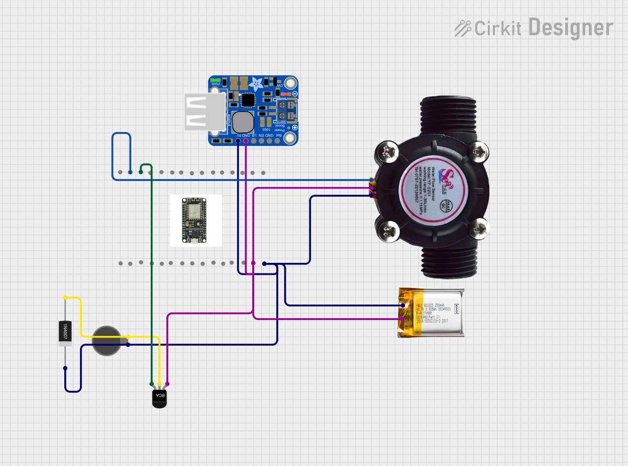
Circuit Documentation
Summary
This circuit is designed to monitor water flow using a flow sensor and provide a reminder via a vibration motor if no flow is detected for a specified interval. The circuit is powered by a 3.7V LiPo battery and includes an ESP8266 NodeMCU microcontroller for processing and control.
Component List
ESP8266 NodeMCU
- Description: A low-cost Wi-Fi microcontroller with GPIO pins.
- Pins: D0, D1, D2, D3, D4, 3V3, GND, D5, D6, D7, D8, RX, TX, A0, RSV, SD3, SD2, SD1, CMD, SD0, CLK, EN, RST, VIN
Water Flow Sensor
- Description: A sensor that measures the rate of water flow.
- Pins: Signal, Vcc, GND
Vibration Motor
- Description: A small motor that provides haptic feedback through vibration.
- Pins: +, -
NPN Transistor
- Description: A transistor used to switch the vibration motor on and off.
- Pins: E (Emitter), C (Collector), B (Base)
1N4007 Rectifier Diode
- Description: A diode used to protect the circuit from reverse voltage.
- Pins: Cathode, Anode
PowerBoost 1000 Basic Terminal USB
- Description: A power supply module that boosts the voltage from a LiPo battery to 5V.
- Pins: VBAT, GND, ENABLE, LBO, 5.0V
3.7V LiPo Battery
- Description: A rechargeable lithium polymer battery.
- Pins: +Ve, GND
Wiring Details
ESP8266 NodeMCU
- D1 is connected to Signal of the Water Flow Sensor.
- D2 is connected to B (Base) of the NPN Transistor.
- GND is connected to:
- GND of the 3.7V LiPo Battery
- GND of the Water Flow Sensor
- E (Emitter) of the NPN Transistor
- GND of the PowerBoost 1000 Basic Terminal USB
- VIN is connected to:
- +Ve of the 3.7V LiPo Battery
- Vcc of the Water Flow Sensor
- Cathode of the 1N4007 Rectifier Diode
- 5.0V of the PowerBoost 1000 Basic Terminal USB
Water Flow Sensor
- Signal is connected to D1 of the ESP8266 NodeMCU.
- Vcc is connected to VIN of the ESP8266 NodeMCU.
- GND is connected to GND of the ESP8266 NodeMCU.
Vibration Motor
- + is connected to VIN of the ESP8266 NodeMCU.
- - is connected to C (Collector) of the NPN Transistor.
NPN Transistor
- E (Emitter) is connected to GND of the ESP8266 NodeMCU.
- C (Collector) is connected to - of the Vibration Motor.
- B (Base) is connected to D2 of the ESP8266 NodeMCU.
1N4007 Rectifier Diode
- Cathode is connected to VIN of the ESP8266 NodeMCU.
- Anode is connected to C (Collector) of the NPN Transistor.
PowerBoost 1000 Basic Terminal USB
- VBAT is connected to +Ve of the 3.7V LiPo Battery.
- GND is connected to GND of the ESP8266 NodeMCU.
- 5.0V is connected to VIN of the ESP8266 NodeMCU.
3.7V LiPo Battery
- +Ve is connected to VIN of the ESP8266 NodeMCU.
- GND is connected to GND of the ESP8266 NodeMCU.
Code Documentation
#include <AntoCommon.h>
#include <AntoHTTP.h>
#include <AntoIO.h>
#include <AntoMQTT.h>
#include <AntoWiFi.h>
#include <AntaresESP8266MQTT.h>
#include <ArduinoJson.h>
#include <ArduinoJson.hpp>
#include <PubSubClient.h>
#include <AntaresESP8266HTTP.h>
#include <ArduinoJson.h>
#include <ArduinoJson.hpp>
#include <Ambient.h>
#include <Adafruit_ESP8266.h>

// Pin assignments
#define FLOW_SENSOR_PIN D1  // GPIO5
#define VIBRATOR_PIN D2     // GPIO4

// Variables
volatile int flowPulseCount = 0; // Flow sensor pulse count
unsigned long lastReminderTime = 0; // Time since last reminder
unsigned long reminderInterval = 60000; // Reminder interval in milliseconds (1 minute)

// Interrupt service routine for flow sensor
void pulseCounter() {
  flowPulseCount++;
}

void setup() {
  // Initialize serial monitor
  Serial.begin(9600);

  // Set up flow sensor
  pinMode(FLOW_SENSOR_PIN, INPUT_PULLUP);
  attachInterrupt(digitalPinToInterrupt(FLOW_SENSOR_PIN), pulseCounter, FALLING);

  // Set up vibrator motor
  pinMode(VIBRATOR_PIN, OUTPUT);
  digitalWrite(VIBRATOR_PIN, LOW); // Ensure motor is off
}

void loop() {
  // Calculate flow rate (assuming a specific sensor)
  float flowRate = (flowPulseCount / 7.5); // Example conversion factor (depends on sensor)
  flowPulseCount = 0; // Reset pulse count
  Serial.print("Flow Rate: ");
  Serial.print(flowRate);
  Serial.println(" L/min");

  // Check if flow rate is zero for a certain interval
  if (flowRate == 0 && millis() - lastReminderTime > reminderInterval) {
    // Trigger the vibrator motor
    digitalWrite(VIBRATOR_PIN, HIGH);
    delay(1000); // Vibrate for 1 second
    digitalWrite(VIBRATOR_PIN, LOW);
    lastReminderTime = millis(); // Update reminder time
  }

  delay(1000); // Delay for reading stability
}
This code sets up the ESP8266 NodeMCU to monitor the water flow sensor and control the vibration motor. The flow sensor's pulse count is used to calculate the flow rate, and if no flow is detected for a specified interval, the vibration motor is triggered to provide a reminder.